


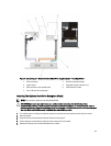
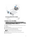
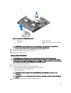
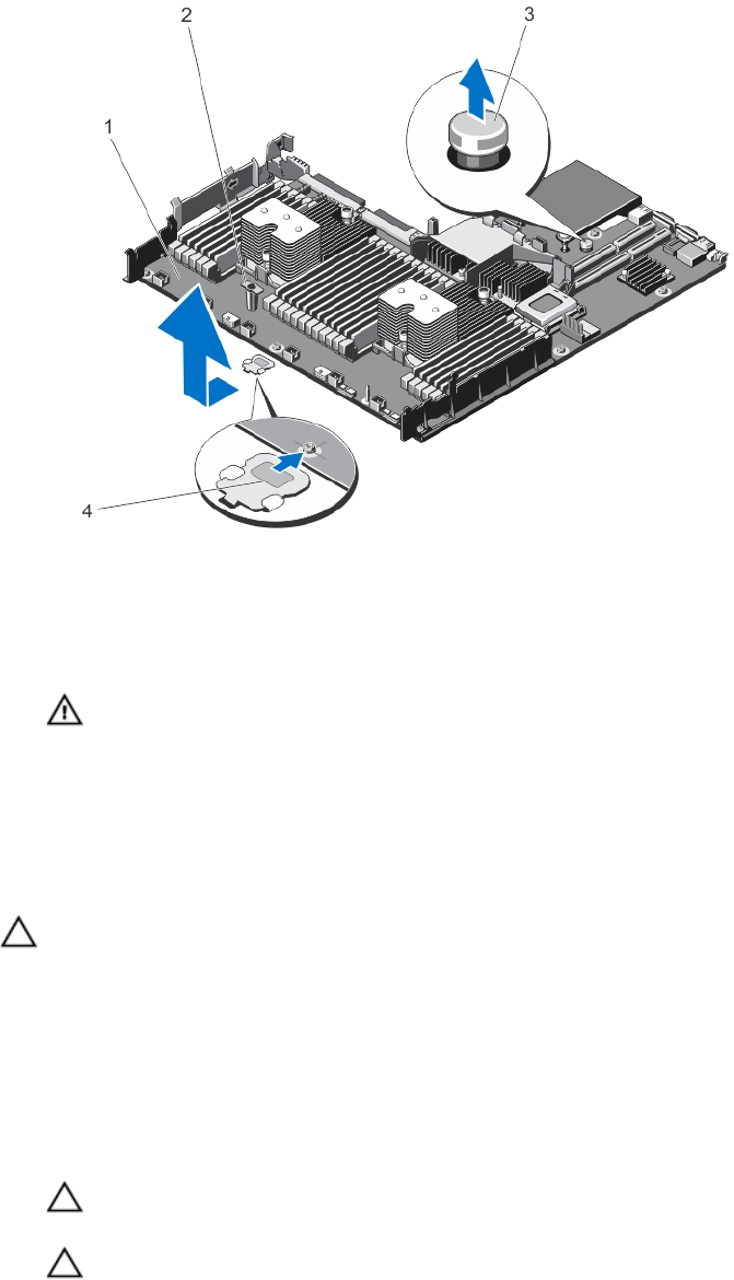
Figure 77. Removing and Installing the System Board
1. system board 2. system-board holder
3. release pin 4. support bracket (present on certain systems
only)
WARNING: The heat sink and processor are hot to the touch for some time after the system has been
powered down. Allow the heat sink and processor to cool before handling them.
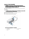
8. Remove heat sink(s)/heat-sink blank(s) and processors(s)/processor blank(s).
9. Remove memory modules and memory module blanks.
10. Remove network daughter card.
Installing The System Board
CAUTION: Many repairs may only be done by a certified service technician. You should only perform
troubleshooting and simple repairs as authorized in your product documentation, or as directed by the online or
telephone service and support team. Damage due to servicing that is not authorized by Dell is not covered by your
warranty. Read and follow the safety instructions that came with the product.
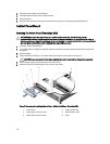
1. Unpack the new system board assembly.
2. Transfer the following components to the new system board:
a. heat sink(s)/heat-sink blank(s) and processors(s)/processor blank(s)
b. memory modules and memory module blanks
c. network daughter card
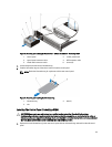
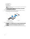
CAUTION: Do not lift the system board assembly by grasping a memory module, processor, or other
components.
CAUTION: Take care not to damage the system identification button while placing the system board into the
chassis.
3. Hold the touch points and lower the system board into the chassis.
121