


xxii
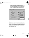
Figure 4-1. ICU Window . . . . . . . . . . . . . . . . . . . . . . . . . . . . . . . . . . . . . . . . . . . 4-5
Figure 4-2. Add Network Card Dialog Box. . . . . . . . . . . . . . . . . . . . . . . . . . . . . . 4-6
Figure 4-3. Card Configuration Dialog Box. . . . . . . . . . . . . . . . . . . . . . . . . . . . . . 4-7
Figure 4-4. Configuration Settings Dialog Box for Assigning an IRQ Line. . . . . . 4-7
Figure 4-5. Available Settings List Box . . . . . . . . . . . . . . . . . . . . . . . . . . . . . . . . 4-8
Figure 4-6. Configuration Settings Dialog Box for Assigning a DMA Channel. . . 4-8
Figure 4-7. Specify Interrupt Dialog Box . . . . . . . . . . . . . . . . . . . . . . . . . . . . . . 4-10
Figure 4-8. Specify Interrupt List Box . . . . . . . . . . . . . . . . . . . . . . . . . . . . . . . . 4-10
Figure 4-9. Specify I/O Port Dialog Box . . . . . . . . . . . . . . . . . . . . . . . . . . . . . . . 4-10
Figure 4-10. System Resource Usage Dialog Box. . . . . . . . . . . . . . . . . . . . . . . . 4-14
Figure 4-11. Card Resource Usage Dialog Box . . . . . . . . . . . . . . . . . . . . . . . . . . 4-14
Figure 5-1. NIC Connector and Indicators . . . . . . . . . . . . . . . . . . . . . . . . . . . . . . 5-2
Figure 5-2. NIC Pop-up Window . . . . . . . . . . . . . . . . . . . . . . . . . . . . . . . . . . . . . 5-7
Figure 6-1. Audio Connectors . . . . . . . . . . . . . . . . . . . . . . . . . . . . . . . . . . . . . . . 6-1
Figure 7-1. Internal Drive Bays . . . . . . . . . . . . . . . . . . . . . . . . . . . . . . . . . . . . . . 7-2
Figure 8-1. Padlock Installed . . . . . . . . . . . . . . . . . . . . . . . . . . . . . . . . . . . . . . . . 8-3
Figure 8-2. Removing the Computer Cover. . . . . . . . . . . . . . . . . . . . . . . . . . . . . 8-3
Figure 8-3. Replacing the Computer Cover . . . . . . . . . . . . . . . . . . . . . . . . . . . . . 8-4
Figure 8-4. Computer Orientation View. . . . . . . . . . . . . . . . . . . . . . . . . . . . . . . . 8-5
Figure 8-5. Inside the Chassis . . . . . . . . . . . . . . . . . . . . . . . . . . . . . . . . . . . . . . 8-6
Figure 8-6. Rotating the Power Supply . . . . . . . . . . . . . . . . . . . . . . . . . . . . . . . . 8-7
Figure 9-1. System Board Features . . . . . . . . . . . . . . . . . . . . . . . . . . . . . . . . . . 9-2
Figure 9-2. Expansion Cards . . . . . . . . . . . . . . . . . . . . . . . . . . . . . . . . . . . . . . . . 9-3
Figure 9-3. Removing the Filler Bracket . . . . . . . . . . . . . . . . . . . . . . . . . . . . . . . 9-4
Figure 9-4. Installing an Expansion Card . . . . . . . . . . . . . . . . . . . . . . . . . . . . . . . 9-5
Figure 9-5. DIMMs and DIMM Sockets . . . . . . . . . . . . . . . . . . . . . . . . . . . . . . . 9-7
Figure 9-6. Installing a DIMM . . . . . . . . . . . . . . . . . . . . . . . . . . . . . . . . . . . . . . . 9-9
Figure 9-7. Removing a DIMM . . . . . . . . . . . . . . . . . . . . . . . . . . . . . . . . . . . . . 9-10
Figure 9-8. SEC Cartridge/Heat Sink Assembly Removal . . . . . . . . . . . . . . . . . 9-12
Figure 9-9. System Battery and Battery Socket . . . . . . . . . . . . . . . . . . . . . . . . 9-15
Figure 10-1. Drive Locations . . . . . . . . . . . . . . . . . . . . . . . . . . . . . . . . . . . . . . . . 10-2
Figure 10-2. Removing the Front-Panel Insert for a 5.25-Inch Bay . . . . . . . . . . . 10-3
Figure 10-3. DC Power Cable Connector. . . . . . . . . . . . . . . . . . . . . . . . . . . . . . . 10-3
Figure 10-4. Drive Interface Connectors . . . . . . . . . . . . . . . . . . . . . . . . . . . . . . . 10-4
Figure 10-5. Removing a Drive . . . . . . . . . . . . . . . . . . . . . . . . . . . . . . . . . . . . . . 10-6
Figure 10-6. Attaching the Drive Bracket to the New Drive . . . . . . . . . . . . . . . . 10-6
Figure 10-7. Inserting the New Drive Into the Drive Bay. . . . . . . . . . . . . . . . . . . 10-7
Figure 10-8. Attaching EIDE Tape Drive Cables . . . . . . . . . . . . . . . . . . . . . . . . . 10-8
Figure 10-9. Removing the Hard-Disk Drive Bracket. . . . . . . . . . . . . . . . . . . . . 10-11
Figure 10-10.Inserting a 1-Inch Hard-Disk Drive Into the Bracket . . . . . . . . . . . 10-12
Figure 10-11.Inserting the Hard-Disk Drive Bracket Into the Chassis . . . . . . . . 10-13
Figure 10-12.Attaching Hard-Disk Drive Cables . . . . . . . . . . . . . . . . . . . . . . . . . 10-14
Figure 10-13.Internal SCSI Cable . . . . . . . . . . . . . . . . . . . . . . . . . . . . . . . . . . . . 10-17
23186bk0.bk Page xxii Thursday, October 29, 1998 11:07 AM