


CANopen Communication Module DVPCOPM-SL
DVP-PLC Application Manual
28
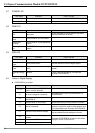
6.1 POWER LED
LED status Indication How to correct
On Power is abnormal. Check the power supply of DVPCOPM-SL.
Green light On Power is normal. --
6.2 RUN LED
LED status Indication How to correct
Off No power
Check the power of DVPCOPM-SL and make
sure the connection is normal.
Green light single
flash
DVPCOPM-SL in STOP status --
Green light
blinking
DVPCOPM-SL in pre-operational
status
--
Green light steady
on
DVPCOPM-SL is operational
status
--
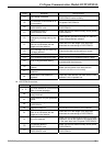
6.3 ERR LED
LED status Indication How to correct
Off Normal --
Red light double
flash
Error control event See the indication from the digital display.
Red light single
flash
Bus error exceeds the warning
limit.
Check if the network connection and operation are
normal.
Red light steady
on
Bus-off
Check if the bus connection is normal and
re-power DVPCOPM-SL.
6.4 Codes in Digital Display
z DVPCOPM-SL as master:
Code Indication How to correct
0 ~ 7F
The node address of DVPCOPM-SL
when in normal operation.
--
F1 No slave configured in node list
Re-configure the node list and download it to
DVPCOPM-SL.
F2
The data are being downloaded to
DVPCOPM-SL.
--
F3 DVPCOPM-SL in error status Check if the wiring of DVPCOPM-SL is correct.
F4 Bus-off is detected.
Make sure the communication cable is in normal
operation, and all the nodes on the network work
in the same baud rate. Re-power DVPCOPM-SL.
F5 Incorrect DVPCOPM-SL settings
Check the settings of node address and baud
rate and make sure the settings are correct.
F6
Internal error: manufacturing
process
F7 Internal error: GPIO check
F8 Internal error: memory check
Re-power DVPCOPM-SL. If the error still exists,
change to a new DVPCOPM-SL.