


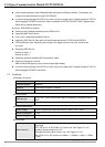

CANopen Communication Module DVPCOPM-SL
DVP-PLC Application Manual
6
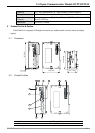
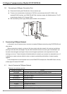
3. POWER, RUN, ERR indicators 8. Function switch
4. DIN rail clip 9. CANopen connection port
5. Digital display
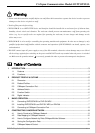
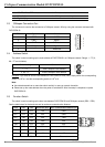
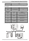
2.3 CANopen Connection Port
The connector is used on the connection to CANopen network. Wire by using the connector enclosed with
DVPCOPM-SL.
PIN Signal Content
1 GND 0 VDC
2 CAN_L Signal-
3 SHLD Shielded
4 CAN_H Signal+
5 - Reserved
4
GND
SHLD
CAN-
CAN+
5
3
2
1
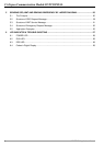
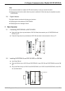
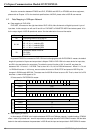
2.4 Address Switch
The switch is used on setting up the node address of DVPCOPM-SL on CANopen network. Range: 1 ~ 7F (0,
88 ~ FF are forbidden).
Switch setting Content
1 ~ 7F Valid CANopen node address
0, 80 ~ FF Invalid CANopen node address
NODE ADDRESS
x16
0
x16
1
Example: If you need to set the node address of DVPCOPM-SL to 26 (1AH), simply switch the corresponding
switch of x16
1
to 1 and the corresponding switch of x16
0
to A.
Note:
z Use slotted screwdriver to rotate the switch carefully in case you scratch the switch.
z Please set up the node address when the power is switched off. After the setup is completed, re-poser
DVPCOPM-SL.
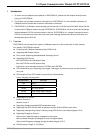
2.5 Function Switch
The switch is used on setting up the baud rate between DVPCOPM-SL and CANopen network (DR0 ~ DR2).
See the table below for the baud rate and its maximum communication distance.
DR2 DR1 DR0 Baud rate (bps) Max. communication distance (m)
OFF OFF OFF 10k 5,000
OFF OFF ON 20k 2,500
OFF ON OFF 50k 1,000
OFF ON ON 125k 500
ON OFF OFF 250k 250
ON OFF ON 500k 100
ON ON OFF 800k 50
ON ON ON 1M 25
IN0 Reserved