


CANopen Communication Module DVPCOPM-SL
DVP-PLC Application Manual
7
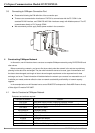
Note:
z Use slotted screwdriver to adjust the DIP switch carefully in case you scratch the switch.
z Please set up the function switch when the power is switched off. After the setup is completed, re-power
DVPCOPM-SL.
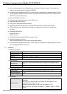
2.6 Digital Indicator
The digital indicator provides the following two functions:
z Displaying the node address of DVPCOPM-SL.
z Displaying the error message of slave.
3 Basic Operation
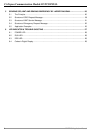
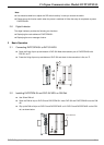
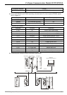
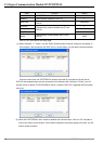
3.1 Connecting DVPCOPM-SL to DVP-SV MPU
z Open the fixing clip on top and bottom of DVP-SV. Meet the extension port of DVPCOPM-SL with
DVP-SV, as
1.
z Press the fixing clips on top and bottom of DVP-SV and check is the connection is fine, as
2.
DVP28SV
RUN
STOP
2
2
11
GND
SHLD
CAN-
NODE ADDRESS
DR 1
IN 0
DR 0
DR 2
x16
0
x16
1
ERR
RUN
POWER
DVPCOPM
CAN+
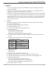
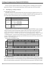
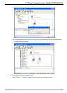
3.2 Installing DVPCOPM-SL and DVP-SV MPU on DIN Rail
z Use 35mm DIN rail
z Open the DIN rail clip on DVP-SV and DVPCOPM-SL. Insert DVP-SV and DVPCOPM-SL onto the DIN
rail.
z Clip up the DIN rail clips on DVP-SV and DVPCOPM-SL to fix DVP-SV and DVPCOPM-SL on the DIN
rail, as shown below.
35mm DIN rail
DVP28SV
RUN
STOP
GND
SHLD
CAN-
NODEADDRE SS
DR 1
IN 0
DR 0
DR 2
x16
0
x16
1
ERR
RUN
POWER
DVPCOPM
CAN+