


35
About the Development Board
CHAPTER 2
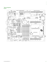
The NS9210 Processor Module Development board supports the NS9210 Processor
Module. This chapter describes the components of the development board and
explains how to configure the board for your requirements.
The development board has two 4x20 pin connectors that are 1:1 copies of the
module pins.
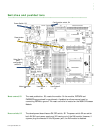
What’s on the
development
board?
RJ-45 Ethernet connector
2 x RP-SMA antenna connectors (reserved for future use)
Four serial interface connectors:
1 x UART B MEI (RS232/RS4xx) with status LEDs on SUB-D 9-pin connector (X6)
1 x UART D RS232 with status LEDs, on SUB-D 9-pin connector (X3)
1 x UART C with TTL levels shared with HDLC signals on 10-pin header (X5)
1 x UART A with TTL levels shared with SPI signals on 10-pin header (X4)
ADC, SPI, and I2C headers
JTAG connector
Peripheral application header
Including access to 16-bit data/10-bit address bus signals
Headers with 1:1 copies of the module pins (X1/X2)
Two user pushbuttons, two user LEDs, wake-up button
Eight-position configuration dip switches
Four each for hardware/software configuration
GPIO screw-flange connector