


40 NS9210 Processor Module Hardware Reference
Chapter 2
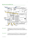
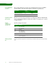
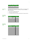
User pushbuttons,
S6 and S7
Use the user pushbuttons to interact with the applications running on the NS9210
Processor Module. Use these module signals to implement the pushbuttons:
Legend for multi-
pin switches
Switches 1 and 4 are multi-pin switches. In the description tables for these switches,
the pin is designated as S[switch number].[pin number]. For example, pin 1 in switch
4 is specified as S4.1.
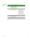
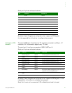
Module
configuration
switches, S4
Use S4 to configure the module:
Wake-up button,
S8
The wake-up pushbutton, S8, generates an external interrupt to the module's NS9215 processor using the EIRQ2
signal.
Signal name Switch
(pushbutton)
GPIO used
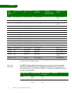
USER_PUSH_BUTTON_1 S6 GPIO81
USER_PUSH_BUTTON_2 S7 GPIO84
Switch pin Function
S4.1 On = Little endian
Off = Big endian
S4.2 Not used
S4.3 On = ARM Debug
Off = Boundary Scan
S4.4 Not used
S4.5 – S4.8 Not defined. Software configuration signals, which can be available for user
specific configuration.