


62 NS9210 Processor Module Hardware Reference
Chapter 2
. . . . . . . . . . . . . . . . . . . . . . . . . . . . . . . . . . . . . . . . . . . . . . . . . . . . . . . . . . . . . . . . . . . . . . . . . . . . . . . . . .
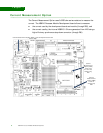
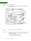
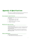
Module and test connectors
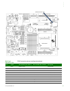
The NS9210 Processor Module plugs into the module connectors X1 and X2 on the
development board.
Module
connectors
See “Module pinout” on page 12 for related information.
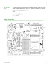
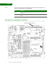
Test connectors The development board provides two 4x20 pin test connectors, labeled X10/X11 and
X20/X21. These connectors are 1:1 copies of the module pins and are used for
measurement or test purposes.
X10 and X11 correspond to module connector X1.
X20 and X21 correspond to module connector X2.
Module
connector,
X1
Module
connector,
X2
Test
connector,
X20, X21
Test
Connector,
X10, X11