


58 NS9210 Processor Module Hardware Reference
Chapter 2
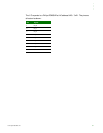
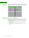
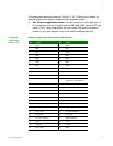
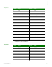
X9 This is how the PoE input connector pins are allocated:
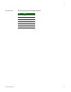
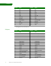
X26 This is how the PoE output connector pins are allocated:
POE_GND The development board provides access to POE_GND allowing it to be turned off
when power is provided through Power Jack X26.4 and X26.5.
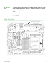
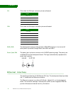
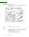
Power Jack, X24 The power jack is a barrel connector with 9-30VDC operating range. The power jack
is labeled X24 on the development board. This figure schematically represents the
power jack’s polarity.
. . . . . . . . . . . . . . . . . . . . . . . . . . . . . . . . . . . . . . . . . . . . . . . . . . . . . . . . . . . . . . . . . . . . . . . . . . . . . . . . . .
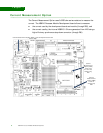
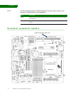
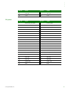
Ethernet interface
The module provides the 10/100 Ethernet PHY chip. The development board provides
the 1:1 transformer and Ethernet connector.
The Ethernet connector is an 8-wire RJ-45 jack, labeled
X19, on the development
board. The connector has eight interface pins, as well as two integrated LEDs that
provide link status and network activity information.
Pin Signal
1 POE_TX_CT
2 POE_RX_CT
3 POE_RJ45_4/5
4 POE_RJ45_7/8
Pin Signal
1 +12V_PoE
2 +12V_PoE
3 GND
4 GND
5 PoE_GND
6 PoE_GND