


. . . . .
www.digiembedded.com 71
. . . . . . . . . . . . . . . . . . . . . . . . . . . . . . . . . . . . . . . . . . . . . . . . . . . . . . . . . . . . . . . . . . . . . . . . . . . . . . . . . .
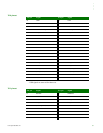
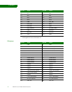
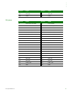
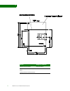
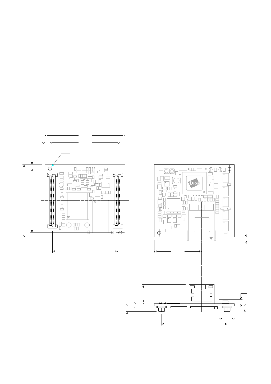
Layout recommendation
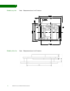
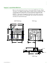
Below are the mechanical dimensions of the standard NS9210 Processor Module.
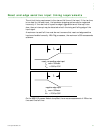
The layout of the NS9210 Processor Module JumpStart board is consistent with the
recommendations from Berg/FCI for the mating connector (Berg/FCI 61083-
084409LF). There is a 41mm separation between the two module connectors.
Drawing number 61083 on the FCI web page: www.fciconnect.com shows the
manufacturer recommended layout.
BOTTOM View
TOP View
2x Ӆ2.20
3.00 44.00
50.00
3.0044.00
50.00
X1 X2
29.50
2.50
3.75
1.40
41.00
6.00
max 2.2mm
max 3mm
13.55
X3
SIDE View
41.00
12
79 80 8079
1
2