


5 Configuration D-Link Web Smart Switch User Manual
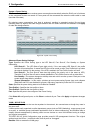
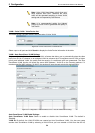
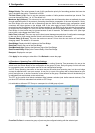
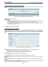
Bridge Priori
ty: This value between 0 and 61410 specifies the priority for forwarding packets: the lower the
value, the higher the priority. The default is 32768.
TX Hold Count (1-10): Used to set the maximum number of Hello packets transmitted per interval. The
count can be specified from 1 to 10. The default is 6.
Maximum Age (6-40 sec): This value may be set to ensure that old information does not endlessly circulate
through redundant paths in the network, preventing the effective propagation of the new information. Set by
the Root Bridge, this value will aid in determining that the Switch has spanning tree configuration values
consistent with other devices on the bridged LAN. If the value ages out and a BPDU has still not been
received from the Root Bridge, the Switch will start sending its own BPDU to all other switches for permission
to become the Root Bridge. If it turns out that the Switch has the lowest Bridge Identifier, it will become the
Root Bridge. A time interval may be chosen between 6 and 40 seconds. The default value is 20. (Max Age
has to have a value bigger th
ello Time (1-10 sec): The user may set the time interval between transmissions of configuration messages
s.
an Hello Time)
H
by the root device, thus stating that the Switch is still functioning. The default is 2 second
Forward Delay (4-30 sec): This sets the maximum amount of time that the root device will wait before
changing states. The default is 15 seconds.
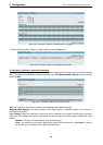
Root Bridge: Displays the MAC address of the Root Bridge.
Root Cost: Display the cost of the Root Bridge.
Root Maximum Age: Displays the Maximum Age of the Root Bridge.
Root Forward Delay: Displays the Forward Delay of the Root Bridge.
Root port: Displays the root port.
Click Apply for the settings to take effect. Click Refresh to renew the page.
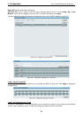
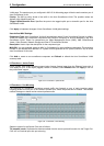
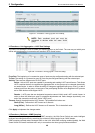
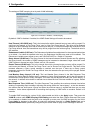
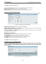
L2 Functions > Spanning Tree > STP Port Settings
STP can be set up on a port per port basis. In addition to setting Spanning Tree parameters for use on the
switch level, the Switch allows for the configuration of the groups of ports, each port-group of which will have
its own spanning tree, and will require some of its own configuration settings.
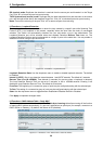
An STP Group spanning tree works in the same way as the
concept is replaced with a root port concept. A root port is a
switch-level spanning tree, but the root bridge
port of the group that is elected based on port
network for the group. Redundant links will be blocked, just
s (and similar network devices). The
links within an STP Group.
.
priority and port cost, to be the connection to the
as redundant links are blocked on the switch level.
The STP on the switch level blocks redundant links between switche
port level STP will block redundant
It is advisable to define an STP Group to correspond to a VLAN group of ports
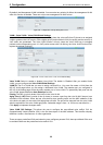
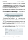
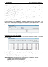
Figure 5.40 – L2 Functions > Spanning Tree > STP Port Settings
From Port/To Port: A consecutive group of ports may be configured starting with the selected port.
38