


19
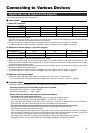
Signals that can be input into the projector
The following signals can be input to the projector.
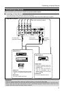
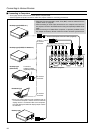
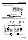
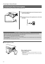
Connecting to Various Devices
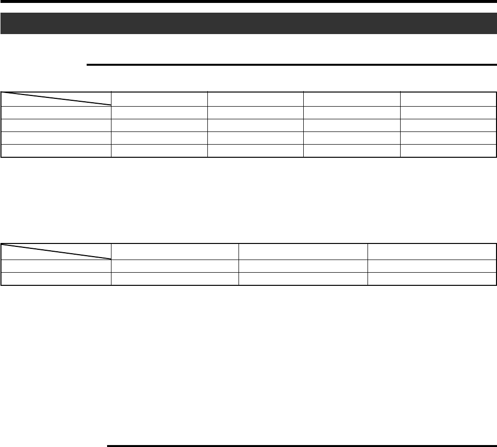
Ⅵ Video signals
(1) Response to Decoder
NTSC NTSC4.43 PAL SECAM
VIDEO O O O O
Y/C O O*
1
O –––––
Y, P B/CB,PR/CR*
3
O*
2
O*
2
O*
2
O*
2
G,B,R,H/Cs,V*
4
O*
2
O*
2
O*
2
O*
2
*
1
: Responds if Y/C output is available.
*
2
: Signifies that component signals (Y, PB, PR/Y, B-Y, R-Y/G, B, R, H/Cs, V) conform to the signal timing (synchronization and video
period ) of each decoder. The decoders are used for convenience.
*
3
:To use these signals, it is required to set the “PC2 (BNC)” item in the “Options” menu to “YPBPR”. (☞ page 39)
*
4
:To use these signals, it is required to set the “PC2 (BNC)” item in the “Options” menu to “RGB”. (☞ page 39)
(2) Responds to double density(*
5
), high-vision signals.
NTSC*
6
PAL*
7
High-vision signal
Y, P B/CB,PR/CR*
8
OOO
G,B,R,H/Cs,V*
9
OOO
*
5
: Signals of which density of scanning lines per field is twice as high.
*
6
: Responds to signals of which the horizontal scanning frequency is 33.25kHz. NTSC can be made twice as dense by a line
doubler (separately available: recommended article). It can also respond to fully-specified, decoded wide-clear-vision signals
and decoded 525p progressive signals.
*
7
: Responds to signals of which the horizontal scanning frequency is 33.5kHz. PAL can be made twice as dense by a line doubler
(separately available: recommended article).
*
8
:To use these signals, it is required to set the “PC2(BNC)” item in the “Options” menu to “YPBPR”.(☞ page 39)
*
9
:To use these signals, it is required to set the “PC2(BNC)” item in the “Options” menu to “RGB”.(☞ page 39)
(3) Response to DTV-format signals
DTV-format signals (480i, 480p, 720p, 1080i) can be input to the Y, PB/CB, PR/CR*
10
input terminals.
*
10
: To use these signals, it is required to set the “PC2(BNC)” item in the menu “Option” to “YPBPR”.(☞ page 39)
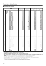
Ⅵ Computer signals
● Computer signals can be input to the PC1, PC2 (G,B,R,H/Cs,V) or PC3 (DVI-D) terminals.
Scanning frequencies in the following ranges can be inputted.
Horizontal scanning frequency : 15kHz ~ 120kHz
Vertical scanning frequency : 50Hz ~ 120Hz
Be sure that the computer used meets the following conditions.
• The computer has a video signal output port.
Confirm if the computer has a video signal output port by consulting the computer’s manual.
The video signal output port is generally called ‘RGB port’, ‘monitor port’, or ‘video port’.
In the case where the computer comes with a built-in monitor, eg; a notebook, an external output port may need to be
purchased. Also, note that an external output port cannot be installed in some computers.
• The resolution and the scanning frequencies are within the range specified in the table on page 20.
Be sure that the resolution and the scanning frequencies of the video signal are within this range.
Video signals out of this range should not be used.
(Out of range signals can be projected but the image may not turn out sharp. Signals within the range may occasionally
require adjustment, depending on the video board used). When signals other than those listed in the table on page 19 are
input, the image could be partially erased or unwanted folds-over the image could appear.
Some signals within the frequency range may not be displayed normally depending on the type of the signal.
Composite sync (Cs) and G on Sync signals cannot be handled depending on the devices connected.
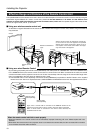
Input terminal
Decoder
Input terminal
Decoder