


9
Controls and Features
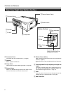
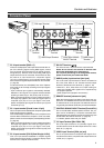
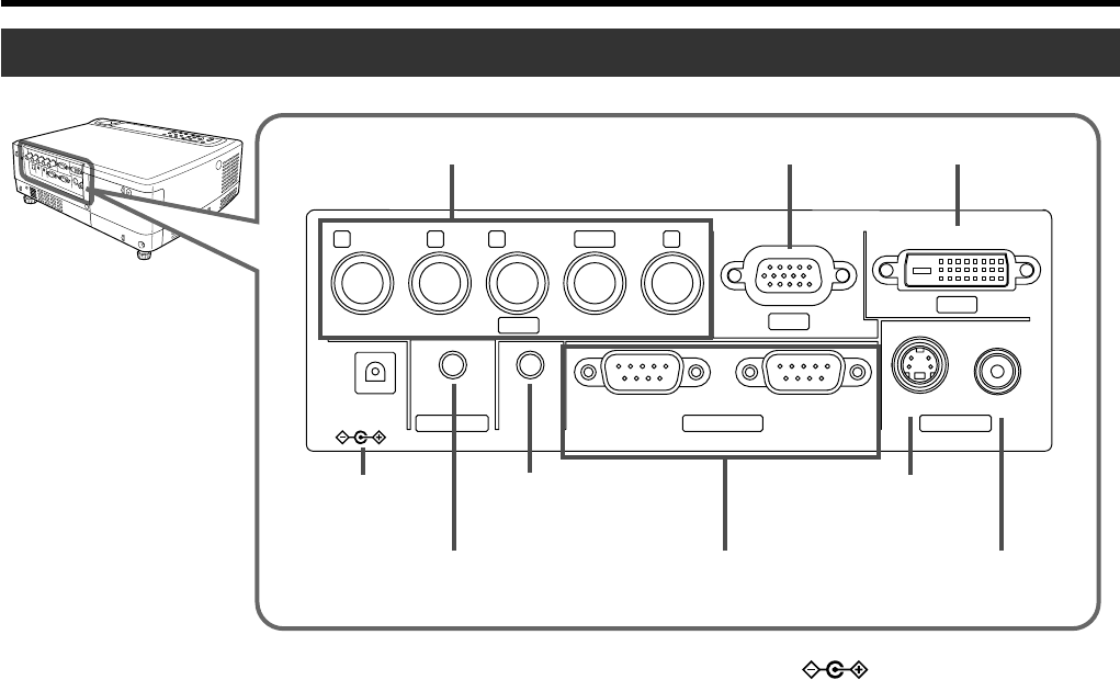
Connector Panel
2
PC1 Input Terminal
4
DC OUT
Ter minal
6
REMOTE
Ter minal
5
AUDIO Input Terminal
7
CONTROL RS232C
IN/OUT Terminal
9
VIDEO Input
Ter minal
1
PC2 Input Terminal
3
PC3 Input Terminal
8
Y/C Input
Ter minal
R
P
R
/C
R
G
Y
B
P
B
/C
S
VDVIH/CS
PC1
PC3
PC2
AUDIO IN
REMOTE
DC OUT
5V }1.5A
RS-232C OUT RS-232C IN Y/C VIDEO
CONTROL VIDEO IN
1 PC 2 Input terminal [BNC x 5]
These are multipurpose video input terminals that allow in-
put of the following signals: analog RGB signals, vertical
sync (V) signals, and horizontal sync (H) signals /compos-
ite signals (Cs). Devices which have analog RGB signal
output terminals can be connected. This terminal can also
be used as an input terminal for component signals
(Y,C
B,CR) or DTV-format (Y, PB,PR) signals. Devices which
have component signals output terminals can be connected.
(☞ page 22)
To use this terminal, the “PC2 (BNC)” item in the “Options”
menu must be set correctly according to the input signals.
(☞ page 39)
* Input of external sync signals is automatically detected.
Detection of H/V signals or Cs signals causes automatic
switching to external sync. The priority order is H/V>Cs.
* When computer signals are input, the uppermost edge of
the image may appear to bow if the sync signal input is a
composite sync (Cs) or G on sync signal. In this case,
please use separate sync signals for vertical sync (V) and
horizontal sync (H).
2 PC 1 input terminal [D-sub 3 rows 15 pin]
This is an input terminal dedicated to computer signals (RGB
Video signals and sync signals).
Connect the display output terminal of the computer to this
terminal. When a Macintosh computer is to be connected,
please use the conversion adapter (sold separately) for Mac.
(☞ page 22)
* When computer signals are input, the uppermost edge of
the image may appear to bow if the sync signal input is a
composite sync (Cs) or G on sync signal. In this case,
please use separate sync signals for vertical sync(V) and
horizontall sync(H).
3 PC 3 input terminal [DVI-D (Dual/ Single) 24 Pin]
This is an input terminal dedicated to computer signals
(DVI-D Terminal Dual/ Single). Connect the display output
terminal of the computer to this terminal.
4 DC OUT Terminal
This is the DC 5V, 1.5A power source output terminal.
Please do not connect this terminal to devices other
than those designated by the manufacturer.
For enquiries pertaining to the designated devices,
please consult with your authorized dealer.
5 AUDIO (audio) input terminal [mini jack]
This is the audio input terminal for devices connected to
PC1, PC2, PC3, Video or Y/C. Connect the audio output
terminal of the device to this terminal. (☞ page 21, 22)
* When PC 1, PC 2, PC3, Video or Y/C input is being se-
lected, the inputted audio signals will be reproduced by
the projector speaker.
(Audio output for this projector is monaural.)
6 REMOTE terminal [stereo mini jack]
When the remote control is unable to work due to rear pro-
jection etc., the REMOTE terminal can be used to connect
an external sensor to the projector. The external sensor is
not generally sold. Please check with your authorized dealer.
7 CONTROL RS232C IN/OUT Terminal [D-sub 9 Pin]
This is the RS-232C interface-specific terminal. The pro-
jector can be controlled by a computer connected exter-
nally. More than one projectors can be controlled using both
the RS-232C IN and OUT terminals. (☞ page 23)
*For details, please check with your dealer.
8 Y/C Input Terminal [Mini DIN 4 PIN]
This is the input terminal for Y/C (S-Video) signals. Con-
nect this terminal to the S-video output terminal of a video
deck, etc. (☞ page 21)
9 VIDEO Input Terminal [RCA pin jack]
This is an input terminal for composite video signals. Con-
nect this terminal to the composite video output terminal of
a VCR, etc. (☞ page 21)