


Page 17
Section 3 – Installation
Dukane Manual Part No. 403-583-00
Power Cords
200/240 Volt Systems
The IEC AC power inlet connector mounted on the rear
panel requires a properly congured IEC compliant power
cord.
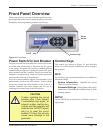
The 200/240 AC power cords supplied with the
generators are matched to the ultrasonic output power
rating and the continent of specied use. See Table 3-I.
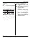
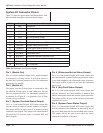
Table 3- I Standard IEC AC Power Cord Part Numbers
100/120 Volt Systems (North America or Japan)
The power cord (including strain relief) supplied with the
100/120 AC systems is permanently attached to the rear
of the generator. Units with this power cord are for use in
North America or Japan.
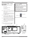
Automation Controlled System
Step 1. Ground the generator chassis using the supplied
14-Gauge wire, and attach it to the grounding
stud:C in Figure 3 -3.
Step 2. Optional – Ground the probe support. This is a
user–supplied 14-Gauge wire.
Step 3. Input/Output Cable - Attach the automation
control cable from the user–supplied automa-
tion equipment to the system HD-15 connector,
INPUTS/OUTPUTS on the rear panel: B in
Figure 3 -3.
Step 4. Attach the high voltage coaxial cable from the
probe to the ultrasound output connector, D in
Figure 3 -3.
Step 5. Connect the AC power cord to the generator
IEC power inlet connector, and plug the other
end into an approved AC outlet:
A in Figure 3 -3.
Continent of Use Power Cord
Part Number
Power
North America 200 - 1541 240V, 10A
Europe 200 - 1542 240V, 10A
India 200 - 1624 240V, 10A