


Page 68
iQ Series, Ultrasonic Hand Held Systems User’s Manual
Dukane Manual Part No. 403-583-00
List of Figures
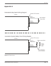
2-1 Example of 125 Volt, Grounded, 3-prong Plug and Receptacle ......................................8
2-2 Example of 250 Volt, Grounded, 3-prong Plug and Receptacle ......................................8
2-3 International 220/240V Grounding ..................................................................................8
3-1 Lockout Device in Open Position, Unlocked .................................................................13
3-2 Bottom Lockout Device in Closed Position, Locked ......................................................13
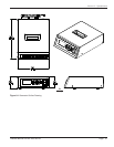
3-3 Generator Detail - Rear Views.......................................................................................16
3-4 Rocker-style Power Switch/Circuit Breaker ...................................................................16
4-1 Front Panel ....................................................................................................................23
4-1A Power Bar Graph - In Cycle ..........................................................................................24
4-1B Power Bar Graph - Operate ..........................................................................................24
4-2 Power Switch .................................................................................................................25
4-3 Power-up Screen 1 ........................................................................................................25
4-3A Power-up Screen 2 ........................................................................................................25
4-3B Operate Screen Appears After Power-up ......................................................................25
4-4 Example of an Operate Screen .....................................................................................26
4-5 Example of an In Cycle Screen .....................................................................................26
5-1 Manual Weld Mode........................................................................................................30
5-2 Navigate to Time Mode .................................................................................................30
5-3 Time Weld Mode - 1 ......................................................................................................30
5-4 Time Weld Mode - 2 ......................................................................................................30
5-5 Time Weld Mode ...........................................................................................................31
5-6 Navigate to Energy Mode -1 ..........................................................................................31
5-6A Navigate to Energy Mode -2 ..........................................................................................31
5-7 Energy Weld Mode - 1 ...................................................................................................31
5-8 Energy Weld Mode - 2 ...................................................................................................31
5-9 HOLD Time - 1 ..............................................................................................................32
5-9A HOLD Time - 2 ..............................................................................................................32
5-10 Amplitude ......................................................................................................................32
5-11 INFO Screen .................................................................................................................33
5-11A System Information Example Screen ............................................................................33
5-12 Warning Screen .............................................................................................................33
5-13 Advanced Settings Screen ............................................................................................33
5-14 Trigger Amplitude ..........................................................................................................34
No. Description Page
Appendix B