


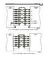
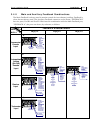
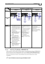
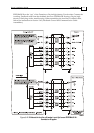
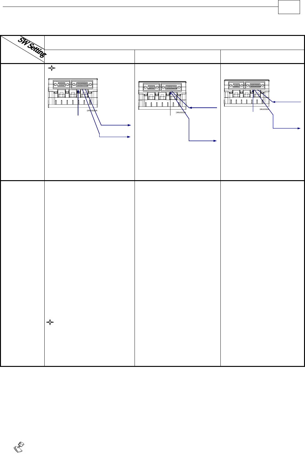
FEEDBACK B Ports B1 and B2
FEED-
BACK A
YA[4] = 4 YA[4] = 2 YA[4] = 0
P
otentiometer
Input
A-input
Potentiometer
Potentiometer
Position Data
Emulated in
Incremental
Encoder
Format
(signals are
quadrature,
differential &
buffered)
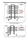
B1- Output
B2- Output
same as B1
Differential
or
Single-ended
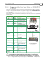
Auxiliary
Incremental
Encoder
B1- Input
B2- Output
Differential
and
Buffered
Auxiliary
Encoder
Signal
Incremental
Encoder
or
Analog
Encoder
or
Resolver
or
Tachometer
or
Potentiometer
or
Absolute
Encoder
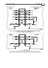
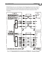
Differential or
Single-ended
Pulse &
Direction
Commands
Differential
and Buffered
Pulse &
Direction
Signals
B1- Input
B2- Output
Incremental
Encoder
or
Analog
Encoder
or
Resolver
or
Tachometer
or
Potentiometer
or
Absolute
Encoder
Typical
Applications
Any application where the
main encoder is used, not
only for the drive, but also
for other purposes such as
position controllers and/or
other drives.
Analog Encoder
applications where position
data is required in the
Encoder’s quadrature
format.
Resolver applications
where position data is
required in the Encoder’s
quadrature format.
Tachometer applications
where velocity data is
required in the Encoder’s
quadrature format.
Absolute Encoder
applications where position
data is required in the
Encoder’s quadrature
format.
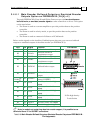
Any application where two
feedbacks are used by the
drive.
Port B1 serves as an input for
the auxiliary incremental
encoder (differential or
single-ended).
Port B2 is used to output
differential buffered
Auxiliary Incremental
Encoder signals.
For applications such as
Follower, ECAM, or Dual
Loop.
Port B1 serves as an input for
Pulse & Direction
commands (differential or
single-ended).
Port B2 is used to output
differential buffered Pulse &
Direction signals.
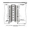
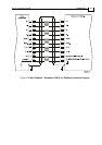
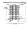
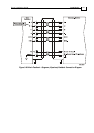
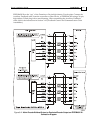
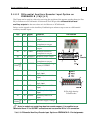
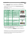
3.4.6 Auxiliary Feedback (FEEDBACK B)
When using one of the auxiliary feedback options, the relevant functionality of FEEDBACK B
ports are software selected for that option. Refer to the SimplIQ Command Reference Manual for
detailed information about FEEDBACK B setup. When assembling the Main Feedback cable,
follow the instructions in Section 3.4.3 (Feedback Control and Communication Cable
Assemblies).
Note: the Feedback connector also supports Feedbacks A and B.
*
Drum Installation Guide Installation
MAN-DRUIG (Ver. 1.0)
3-29