


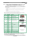
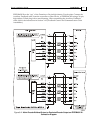
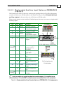
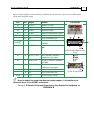
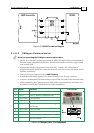

Below are the signals on the Auxiliary Feedback ports when set up to run as a differential
pulse-and-direction input:
Port Pin Signal Function Pin Position
B2 10 CHAO Channel A output
B2 11 CHAO- Channel A complement output
B2 12 CHBO Channel B output.
B2 13 CHBO- Channel B complement output
14 NC Do not connect this pin
15 NC Do not connect this pin
PWR
18 SUPRET Encoder supply voltage return/
COMRET
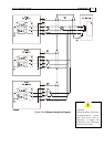
B1 19 PULS/CHA Pulse/Auxiliary channel A high
input
26 Pin D-Sub High Density
Plug
B1 20 PULS-/CHA- Pulse/Auxiliary channel A
complement high input
B1 21 DIR/CHB Direction/Auxiliary channel B
high input
B1 22 DIR-/CHB- Direction/Auxiliary channel B
complement high input
23 NC Do not connect this pin
24 NC Do not connect this pin
PWR 25 +5V Encoder supply voltage
26 Pin D-Sub Socket
Note: In models not containing absolute encoder support, it is possible to use
terminals 16 and 17 for SUPRET connections.
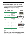
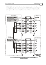
Table 3-12: Differential Pulse-and-Direction Auxiliary Encoder Pin Assignment on
FEEDBACK B
J4
Female
Drum Installation Guide Installation
MAN-DRUIG (Ver. 1.0)
3-38