Functional Description
MITX-430/MITX-440-DVI-2E Installation and Use Guide (6806800K37B)
63
4.9 DVI Interface
The DVI is switched and derived from LVDS, so DVI and LVDS cannot be used at the same time.
For display combination, use VGA + LVDS or VGA + DVI. Select the combination in the BIOS.
4.10 BIOS Device
A 4MB SPI Flash is used as BIOS device.
4.11 IDE
The MITX-430/MITX-440-DVI-2E supports a 44pin Mini-IDE header on board.
The IDE interface supports up to two IDE devices providing an interface for IDE hard disks and
ATAPI devices. Each IDE device has independent timings. The IDE interface supports PIO IDE
transfers up to 16 MB/sec and Ultra ATA transfers up to 100 MB/sec. It does not consume any
legacy DMA resources. The IDE interface integrates 16*32-bit buffers for optimal transfers.
The ICH8s IDE system contains a single, independent IDE signal channel that can be electrically
isolated. There are integrated series resistors on the data and control lines.
4.12 GPIO Configuration
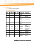
There are two GPIOs:
z User defined GPIO which is generated from PCA9557PW
z ICH8-M GPIO
4.12.1 User Defined GPIO
4 GPI, 4 GPO 5V referenced. The 4 GPOs are internally pulled up to 5V with 10K resistor. The 4
GPIs are internally pulled down to GND with 10K resistor. The GPIO is controlled through SMBus
and the state of GPO is not lost even in S3 and S5 sleep state.


