Installation and start-up 21
Helios Rectifier 25/48 Installation and User Manual
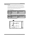
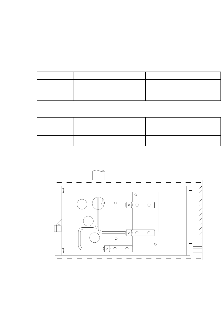
Installing the AC power
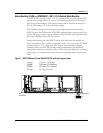
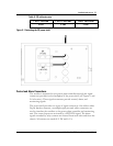
Permanent AC connection to the MPS75 power shelf is done using two
armored cable conductors, RW-90 or equivalent, as listed in Table 2. One
must be routed to L1, and the other one to L2 and to the safety shelf frame
ground (FR GND). The cabling must comply to the local electrical code. The
power shelf is equipped with a strain relief to terminate the conduit. The
cable length should be minimized and be properly secured.
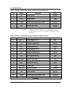
Table 2 - AC cable wire size
2 RECTIFIER POSITIONS 3 RECTIFIER POSITIONS
Individual AC 12 AWG for each rectifier 12 AWG for each rectifier.
Common AC 8 AWG 6 AWG
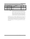
Table 3 - AC Fuses
2 RECTIFIER POSITIONS 3 RECTIFIER POSITIONS
Individual AC 20 A max for each rectifier 20 A max for each rectifier
Common AC 40 A max. 60 A max.
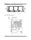
Figure 4 - Power shelf common AC connection
FR GRD
L2
L1


