


Installation and start-up 23
Helios Rectifier 25/48 Installation and User Manual
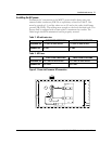
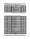
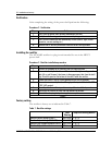
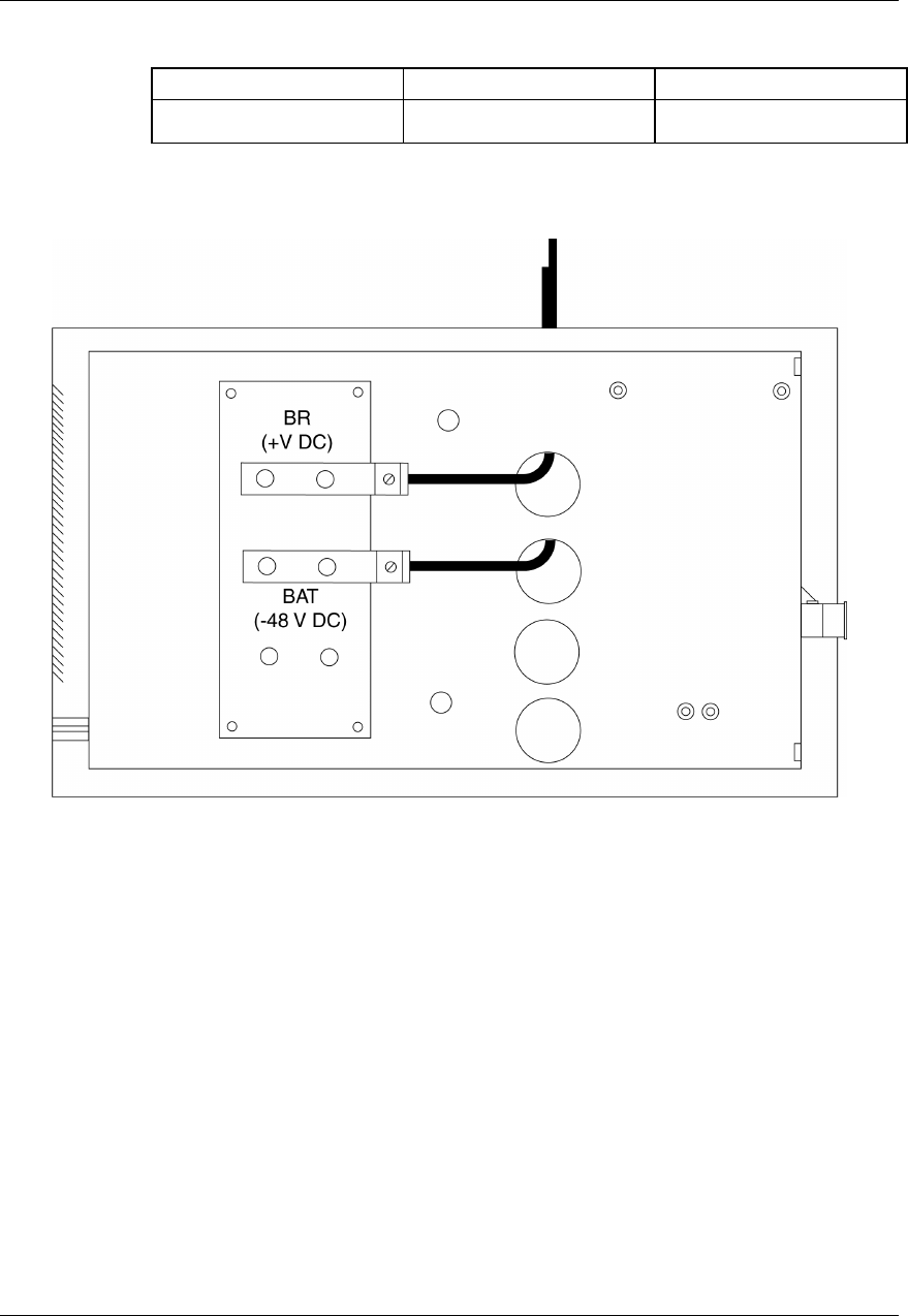
Table 4 - DC cable wire size
1 RECT. POSITION 2 RECT. POSITIONS 3 RECT. POSITIONS
8 AWG 6 AWG 4 AWG
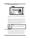
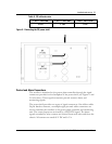
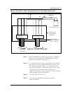
Figure 6 - Connecting the DC power shelf
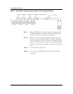
Control and Alarm Connections
The rectifier is interfaced to the power plant controller through the signal
connectors provided on the backplane of the power shelf (see Figures 1 and
2 for location). These signal connectors provide control, alarm, and
monitoring signals.
The power shelf provides two types of signal connectors. One ribbon cable
26-pin female connector, or multiple eight-pin male cable connectors are
used to interface the rectifiers to the power plant controller and monitoring
unit. The control inputs are activated by a BAT RTN signal. The alarm
signals extended by relay contacts are isolated from each other and from the
chassis. All contacts are rated 60 V DC and 0.5 A.