


Installation and start-up 27
Helios Rectifier 25/48 Installation and User Manual
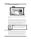
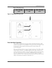
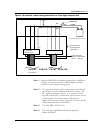
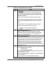
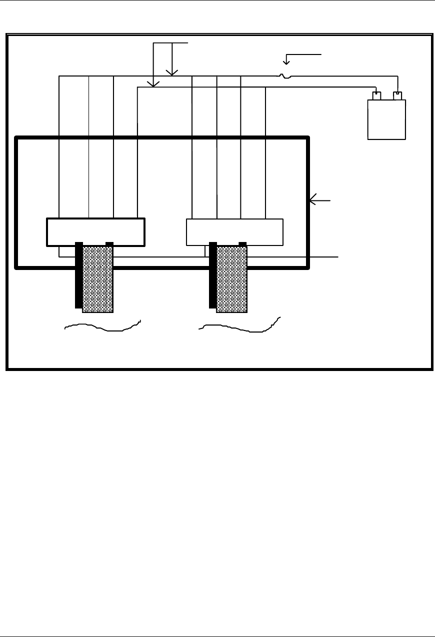
Figure 8 - No controller, remote sensing connection for a 26-pin signal connector shelf
-
+
BATTER
Y
or desired regulation point
RC-
RG+
RC FUSE 1.6 AMP
SEENOTE4
20 AWG (SEE NOTE 3)
1611 20
16
26 pins ribbon
connector mate
Force share line
Shelves interconnect
points
SIGNAL CABLES FROM SHELVES
(PIN 16)
(
see note 1 )
Printed circuit or
wire wrapboard
(Seenote2)
16
Note 1:
Refer to MS5C06 for available signal cables of different
lengths, to connect from the shelf backplane rectifier
position to the remote sensing point.
Note 2:
Use a printed circuit or wire-wrap board to interface all
the 26-pin connector ribbons from all the shelves. All
RC- signal connections (pin 11, 6, 1) must be joined
together. All the RC+ connections (pin 20) must also be
joined together. For forced share current mode
applications, the force share signal (pin 16) must also be
interconnected between the shelves.
Note 3:
Use #20 AWG (105°C) wire.
Note 4:
Use 1.6A fuse A0384386 with ferrule type fuse
holder A0384387.