


24 Installation and start-up
UM5C06D ( 169-2071-504 ) P0831010 Standard 7.00 May 2001
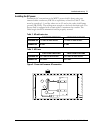
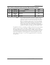
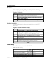
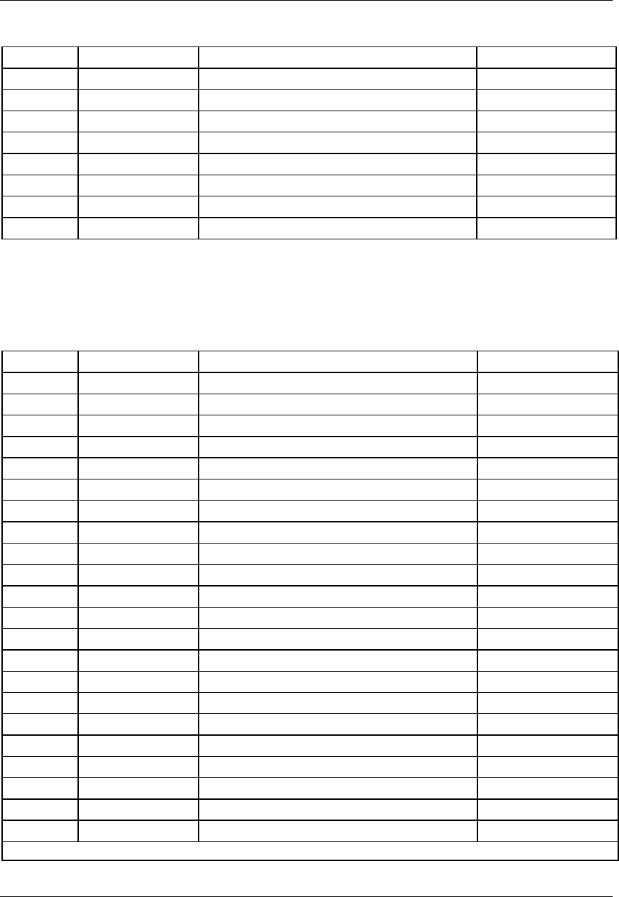
Table 5 - Rectifier and Controller interface connections (8-pin connectors)
Pin # Design. Description Signal
1 EQL Remote Equalize BAT RTN
2 RG+ Sensing Positive BAT RTN
3 RC- Sensing Negative -48V
4 FAN ALM Fan Failure BAT RTN
5 HVSDR Remote High Voltage Shutdown Reset BAT RTN
6 HVSD Remote High Voltage Shutdown BAT RTN
7 RFA Rectifier Failure Alarm BAT RTN
8 TB Temporary Release BAT RTN
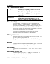
Note:
Both RFA and Fan alarm relays are energized during
normal operation and are de-energized during an alarm
condition.
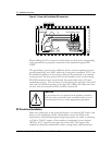
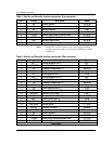
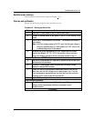
Table 6 - Rectifier and Controller interface connections (26-pin connector)
Pin # Designation Description Signal
1 RC1 - Sensing Negative rect (1) BAT-
2 RFA1 (NC) Rectifier (1) fail alarm NC
3 TR1 Temporary Release Rect (1) Bat RTN
4 SH1+ Shunt Positive Rect (1) 50 mV
5 SH1- Shunt Negative Rect (1) 50 mV
6 RC2- Sensing Negative Rect (2) BAT-
7 RFA2 (NC) Rectifier (2) fail alarm NC
8 TR2 Temporary Release Rect (2) Bat RTN
9 SH2+ Shunt Positive Rect (2) 50 mV
10 SH3- Shunt Negative Rect (3) 50 mV
11 RC3- Sensing Negative Rect (3) BAT-
12 RFA3 (NC) Rectifier (3) fail alarm NC
13 TR3 Temporary Release Rect (3) Bat RTN
14 SH3+ Shunt Positive Rect (3) 50 mV
15 SH3- Shunt Negative Rect (3) 50 mV
16 CUR SHARE Current Share 0 - 12VDC
17 RFA (C) Rectifier Fail Alarm Common
18 ALM COMMON Alarms Common Common
19 EQL Remote Equalize BAT RTN
20 RG+ Sensing Positive BAT RTN
21 HVSDR Remote High Voltage Shutdown Reset BAT RTN
22 HVSD Remote High Voltage Shutdown BAT RTN
continued