


Installation and start-up 25
Helios Rectifier 25/48 Installation and User Manual
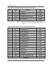
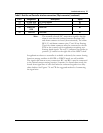
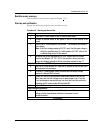
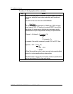
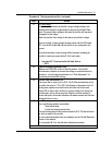
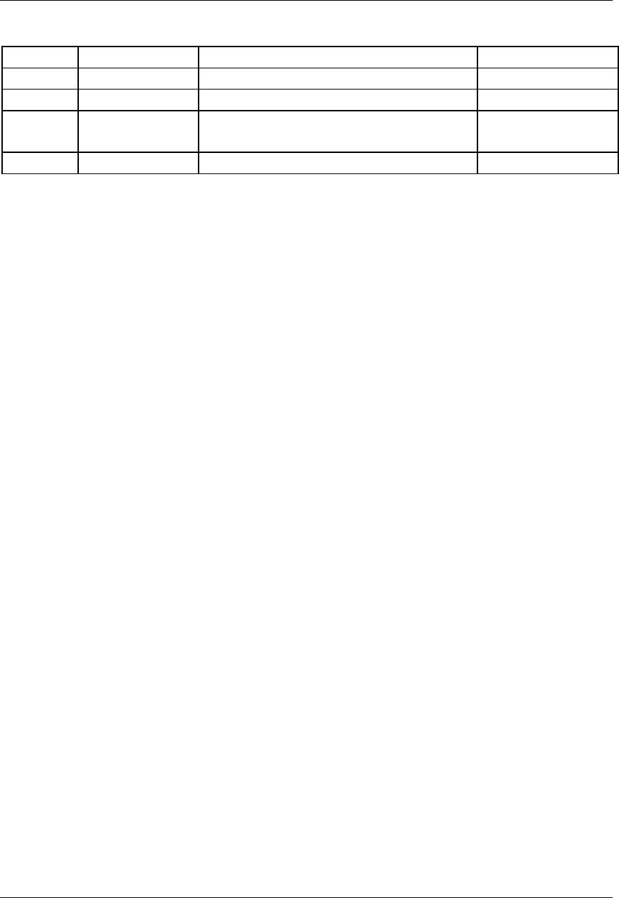
Table 6 - Rectifier and Controller interface connections (26-pin connector) ( continued )
Pin # Designation Description Signal
23 DC BRK ALM DC Circuit Breaker NC
24 AC FAIL ALM AC Line Fail Alarm NC
25 SENSE FAIL
ALM
Sense Fail NC
26 FAN ALM Fan Alarm NC
Note:
The normally closeed (NC) annotation signifies that the
alarm is sent when the contact between the alarm (NC)
and alarm common is closed (short-circuited). The alarm
RFA (C) and alarm common pins 17 and 18 are floating.
These two alarm commons must be connected to the bat
RTN at the system level for applications requiring non-
floating alarm signals. The rect (1) indicates the rectifier in
position (1) located on the right side of the MPS75 shelf.
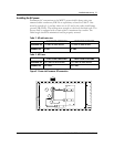
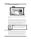
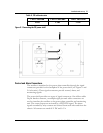
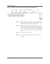
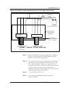
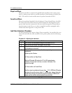
In applications where no controller is available or desired, the current sharing
functions among rectifiers in SLOPE or FORCE mode are still available.
The signal cable remote sense connections RC- and RG+ must be connected
to the desired remote sensing location ( batteries). In forced share mode, the
forced share signal line of each shelf must be connected together in a daisy
chain fashion. See Figures 7A and 7B for suggested methods of connecting
the signal wire.