Contents 9
Helios Rectifier 25/48 Installation and User Manual
RFA fault..............................................................................................................47
SEN FAIL fault......................................................................................................48
Erratic load fault...................................................................................................48
Current or voltage float fault ................................................................................48
Appendix A: Replacement parts.............................................................................. 49
Appendix B: Technical service assistance............................................................. 51
Local toll-free prefixes .................................................................................................51
Toll-free technical assistance numbers.........................................................................52
List of terms and acronyms..................................................................................... 53
List of Figures
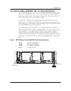
Figure 1 - MPS75 Modular Power Shelf-NT5C10C with 8-pin signal cables .................13
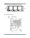
Figure 2 - MPS75 Modular Power shelf- NT5C10C with 26-pin signal connectors........14
Figure 3 - NT5C06D Switch Mode Rectifier.................................................................14
Figure 4 - Power shelf common AC connection.............................................................21
Figure 5 - Power shelf individual AC connection...........................................................22
Figure 6 - Connecting the DC power shelf ....................................................................23
Figure 7 - No controller, remote sensing connection for 8-pin signal cable shelves........26
Figure 8 - No controller, remote sensing connection for a 26-pin signal connector
shelf...........................................................................................................27
Figure 9 - NT5C06D - front view..................................................................................34
Figure 10 - Power interface connections......................................................................39
Figure 11 - Control signal connections .........................................................................40
Figure 12 - NT5C06D rear view...................................................................................44
List of Tables
Table 1 - Electrical specifications.................................................................................15
Table 2 - AC cable wire size.........................................................................................21
Table 3 - AC Fuses.......................................................................................................21
Table 4 - DC cable wire size.........................................................................................23
Table 5 - Rectifier and Controller interface connections (8-pin connectors) ..................24
Table 6 - Rectifier and Controller interface connections (26-pin connector)..................24
Table 7 - Rectifier settings ..........................................................................................28
Table 8 - Indicators......................................................................................................35
Table 9 - System fault diagnosis..................................................................................47
List of Procedures
Procedure 1 - Installing the power shelf.......................................................................20
Procedure 2 - Verification ............................................................................................28
Procedure 3 - Rectifier installation procedure...............................................................28
Procedure 4 - Starting up the rectifier..........................................................................29
Procedure 5 - Adjusting the load share.........................................................................32
Procedure 6 - Adjusting the float / equalize ..................................................................41
Procedure 7 - Replacing the fan ...................................................................................43


