


Introduction
3
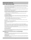
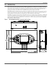
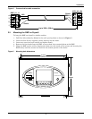
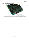
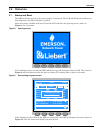
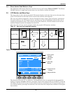
Figure 2 Remote Monitoring Panel layout constraints
Table 1 RMP component location in Figure 1
1 Bypass Input 10 F3 Function Key
2 Inverter—DC to AC 11 F4 Function Key
3 Rectifier—Input AC to DC 12 Help Key
4 Load—AC Output 13 Silence On/Off Audible—Alarm Mute
5 Battery—DC Backup 14 RS-232—for firmware update
6 Audible Alarm—Buzzer 15 RS-232—Reserved, not used
7 UPS Status and Alarm indicator 16 AC power input cable entry
8 F1 Function Key 17 RS-485 communication cable entry
9 F2 Function Key
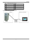
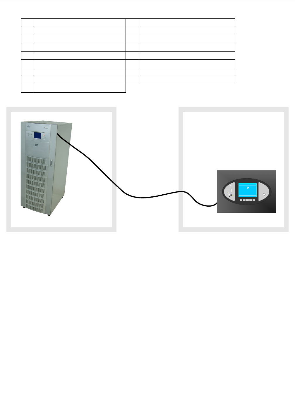
UPS Room
Liebert NX
Communication
Cable; Maxi-
mum Length
100m (328ft.)
(field-supplied)
Maintenance or Control Room
HELPF4F3F2F1
EMERSON
™
Network Power
Liebert
®
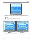
Press any k ey back to m ain menu
Lieber t NX
081 kVA -3x3
12- 16- 2009
Singl e
12:22 : 14
Normal
STATUS
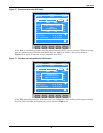
EMERSON
™
Netwo rk Power
SILENCE ON/OFF
Remote Monitor Panel
Liebert
NX