


Hardware Preparation and Installation
RTM-ATCA-F120-OPT Installation and Use (6806800G29C)
31
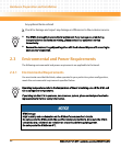
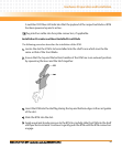
A switched OFF blue LED indicates that the payload of the respective blade or RTM
has been powered up and is active.
13.Plug interface cable into face plate connectors, if applicable.
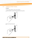
Installation Procedure without Installed Front Blade
The following procedure describes the installation of the RTM.
1. Locate the slot the RTM is to be installed into the shelf's rear which must be the
same as that of the front blade.
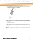
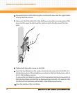
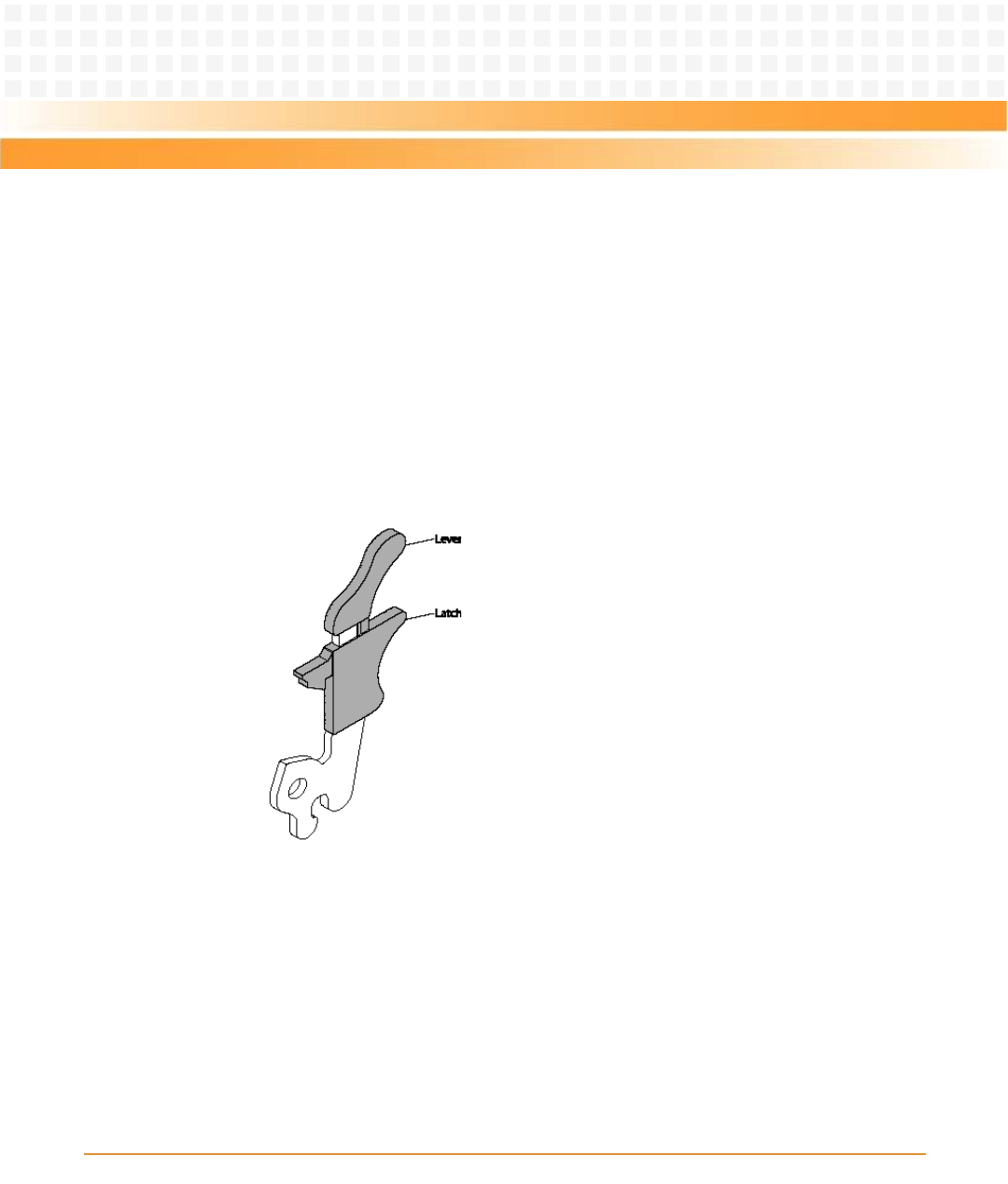
2. Ensure that the top and the bottom handles of the RTM are in an outward position
by squeezing the lever and the latch together.
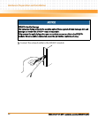
3. Insert the RTM into the shelf by placing the top and bottom edges in the card guides
of the slot.
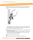
4. Slide the RTM into the slot.
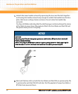
5. Apply equal and steady pressure to the RTM to carefully slide the RTM into the shelf
until you feel resistance. Continue to gently push the RTM until the RTM connectors
engage.