Hardware Preparation and Installation
RTM-ATCA-F120-OPT Installation and Use (6806800G29C)
35
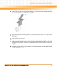
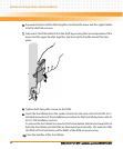
3. Unlatch the upper handle and rotate both handles fully outward.
4. Remove interface cables from face plate connectors, if applicable.
5. Loosen the two RTM face plate screws.
6. Remove the RTM from the slot.
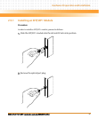
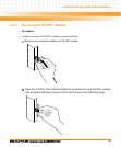
2.5 Installing and Removing SFP/ SFP+ Modules
This section describes how to install and remove SFP and SFP+ modules. For details about
supported SFP/SFP+ modules refer to Interface Connectors on page 43.
Eye Damage
Optical SFP/SFP+ modules may emit laser radiation when no cable is connected.
Avoid staring into open apertures to avoid damage to your eyes.
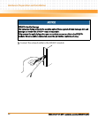
Personal Injury and Damage of the RTM and SFP/SFP+ Modules
Installing and using SFP/SFP+ modules which are not fully certified and which do not meet
all relevant safety standards may damage the RTM and the SFP/SFP+ modules and may lead
to personal injury.
Only use and install SFP/SFP+ modules which are fully certified and which meet all relevant
safety standards.
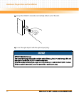
Personal Injury
Optical SFP/SFP+ modules may be classified as laser products. When installing and using any
of these SFP/SFP+ modules, the regulations which correspond to the respective laser class
apply to the whole RTM. Not complying to these regulations, may lead to personal injury.
When installing and using optical SFP/SFP+ modules which are classified as laser products,
make sure to comply to the respective regulations.


