


Liebert XD Cooling Modules—Liebert XDO, Liebert XDV, Liebert XDH and Liebert XDCF
55
4.11 Liebert XDC Standard Features
• Compressors—Scroll with a suction gas cooled motor, vibration isolators, thermal overloads, man-
ual reset high-pressure switch and pump down low-pressure switch.
• Refrigeration System—Dual refrigeration circuits each including liquid line filter dryers, refriger-
ant sight glass with moisture indicator, electronic control valve, adjustable externally equalized
expansion valves and liquid line solenoid valves.
• Heat Exchanger—Brazed plate design with interwoven circuiting constructed of stainless steel
plates, copper brazed. PUMPS Centrifugal type, end suction, canned rotor design.
• Standard Control Processor—The standard control system is microprocessor-based with an exter-
nal LCD numerical display to allow observation of specified adjustable functions. Normal operat-
ing conditions are indicated on the LCD panel, which is mounted either on the unit or on the wall,
depending on application details (see user manual, SL-16671). The control system also monitors
unit operation and activates an alarm when any of the specified factory preset conditions are
exceeded.
• Cabinet and Frame—Custom powder painted steel panels. A hinged control access panel opens to
a second front panel, which is a protected enclosure for all high voltage components. Frame is con-
structed of 14 gauge heliarc welded tubular steel and painted using an auto-deposition coating
system.
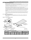
4.11.1 Liebert XDC Optional Features
• Water / Glycol Condensers—A water/glycol floor stand condenser option is available for heat
rejection requirements. The water/glycol floor stand can be located beneath the XDC unit or
installed nearby.
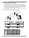
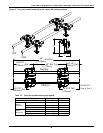
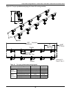
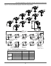
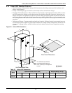
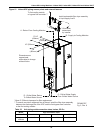
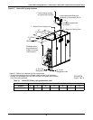
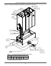
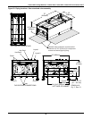
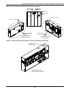
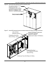
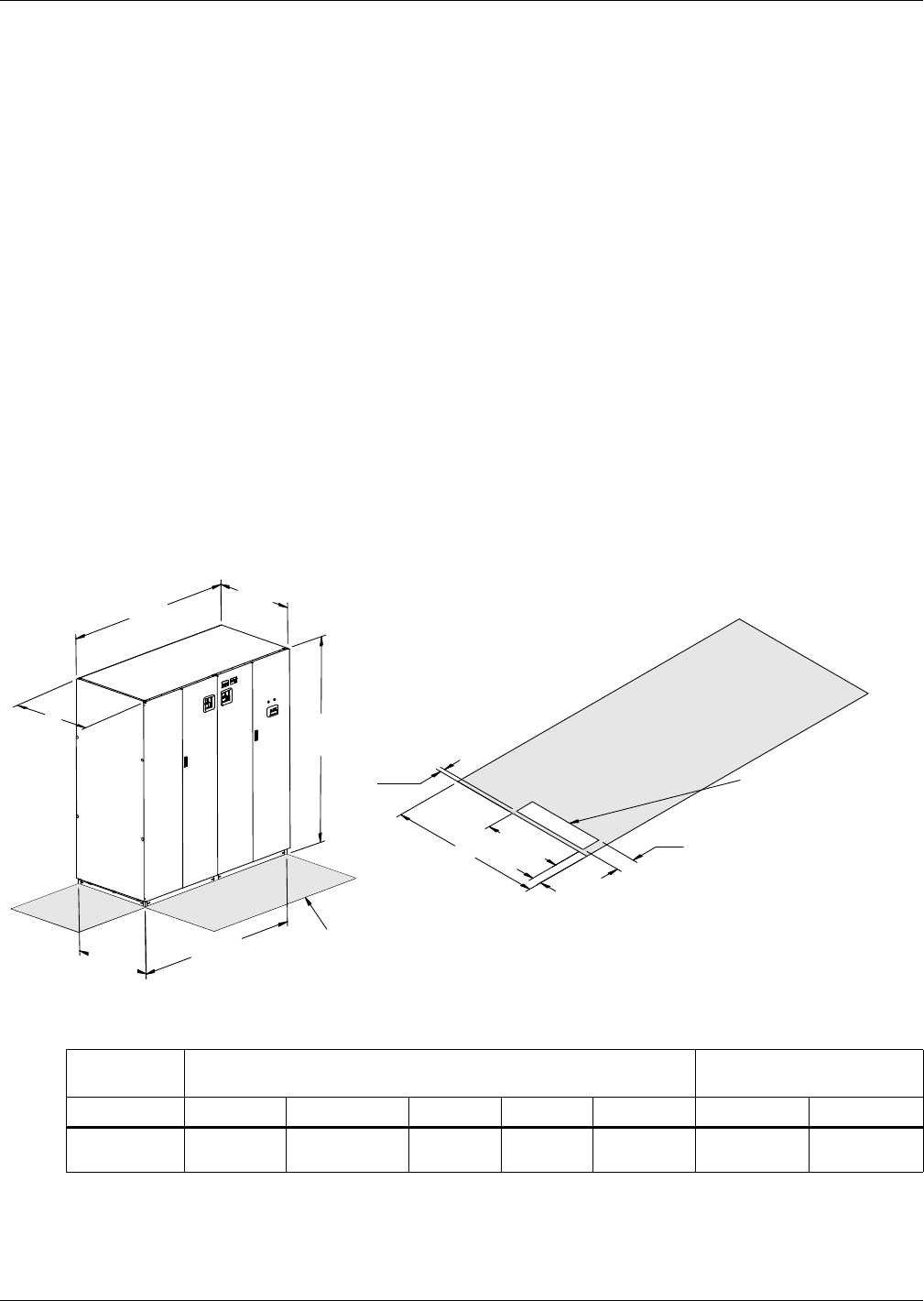
Figure 56 Liebert XDC dimensional data
Table 24 Liebert XD Chiller dimensions, weight
Air Cooled
Model Dimensional Data, inches (mm) Shipping Weight, lb (kg)
50/60Hz A B C D E Domestic Export
Liebert
XDC160
74 (1880) 34 (864)
33-1/8
(841)
33 (838) 72 (1829) 1945 (882) 2093 (949)
* Dimension does not include the bezel of the disconnect switch.
C
D
B
Overall
5"
(127mm)
17"
(432mm)
1"
(25.4mm)
2"
(51mm)
78"
1981mm
A
Overall
Shaded areas indicate a
recommended clearance
of 34" (864mm) for
component access.
D
Unit
Base
E
Unit Base
Unit Dimensional Data
Floor Cutout Dimensions
DPN000768
Page 2, Rev. 6
Recommended
Minimum Hot Gas
Supply & Liquid Return
Piping Opening