


Enterasys NAC Controller Hardware Installation Guide B-1
B
Mode Switch Bank Settings
and Optional Installations
Thisappendixcoversthefollowingitems:
Required Tools
Usethefollowingtoolstoperformtheproceduresprovidedinthisappendix:
•Antistaticwriststrap
• Phillipsscrewdri ver
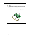
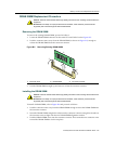
Setting the Mode Switches
Thelocationonthemainboardofthemodeswitchesforboththe2S4082‐25andthe7S4280‐19are
thesame.Figure B‐1showsthelocationofthemodeswitchesandtheswitchsettingsfornormal
operation.Theseswitchesaresetatthefactorytotheoffpositionandrarely
needtobechanged.
Switchdefinitionsandpositionsareasfollows:
•Switches1through6–ForEnterasys Networksuseonly.
•Switch7–ClearPersistentData.ChangingthepositionofthisswitchclearsPersistentDataon
thenextpower‐upofthemodule.Alluser‐enteredparameters,suchastheIPaddress
or
For information about... Refer to page...
Required Tools B-1
Setting the Mode Switches B-1
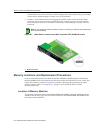
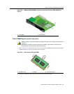
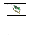
Memory Locations and Replacement Procedures B-2
Caution: An antistatic wrist strap is required to perform the following procedures to minimize ESD
damage to the devices involved.
Precaución: Para minimizar los efectos de las descargas de electricidad estática, deberá utilizar
una pulsera antiestática al realizar los siguiente procedimientos.
Caution: Read the appropriate sections to be fully aware of the consequences when changing
switch settings.
Only qualified personnel should change switch settings.
Precaución: Si desea modificar la configuración del interruptor, lea las secciones
correspondientes para saber cuál será el resultado de hacerlo.
Estas modificaciones a la configuración sólo debe realizarlas personal calificado.