


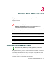


Powering Up a Enterasys Matrix N1 Chassis
Enterasys NAC Controller Hardware Installation Guide 3-5
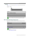
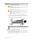
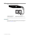
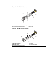
Figure 3-2 ESD Grounding Receptacle
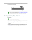
Powering Up a Enterasys Matrix N1 Chassis
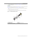
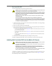
TopowerupaEnterasys Matrix N1Chassiswithacpowersupplies,refertoFigure 3‐3and
proceedasfollows:
1. Plugoneendofeachpowercord(suppliedwiththechassis)intotheacpowersocketsonthe
backoftheN1Chassis.SeeFigure 3‐3onpage 3‐6forthepowerconnections.
2. Plug
eachofthepowercordsintoseparatededicated115Vac,15Areceptacles.
3. EnsurethatthePowerLEDoneachpowersupplyisgreen,locatedonthefrontpanelofthe
N1Chassis.
4. Ensurethatallfansinthefantrayunitareoperatingproperlywhenpowerisreceivedfrom
the
powersupplymodules(fantrayLEDwillbegreen,locatedonthefrontpaneloftheN1
Chassis).FormoreinformationonthepowersupplyLEDs(PowerandFan),referto
“LANVIEWLEDs”onpage 2‐2.
1 ESD grounding receptacle
Note: To install the NAC Controller PEP, refer to the Chapter 4, NAC Controller PEP Installation
section for the installation instructions. Before you power up the Enterasys Matrix N1 Chassis, it is
recommended that you complete the installation of the NAC Controller PEP in the chassis.
FAN
STATUS
PS1
STATUS
PS2
STATUS
N1
GROUND
STRAP
7C111
N1 7C111 d
GROUND
STRAP
N1
1
Note: For power redundancy, each of the power cords from the two power supplies must be
connected to dedicated 15-Ampere ac power circuits.