


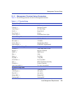

Management Terminal Setup
2-2 Local Management Requirements
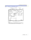
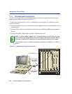
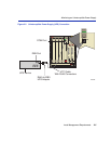
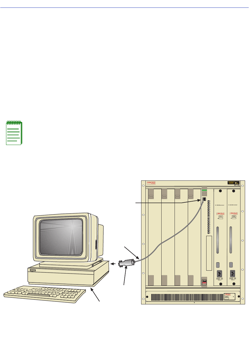
2.1.1 Console Cable Connection
Use the Console Cable Kit provided with the chassis to attach the management terminal to the
switch module COM port as shown in Figure 2-1.
To connect the switch module to a PC or compatible device running the VT terminal emulation,
proceed as follows:
1. Connect the RJ45 connector at one end of the cable (supplied in the kit) to the COM port on the
switch module.
2. Plug the RJ45 connector at the other end of the cable into the RJ45-to-DB9 adapter (supplied in
the kit).
3. Connect the RJ45-to-DB9 adapter to the PC communications port.
Figure 2-1 Management Terminal Connection
NOTE: If using a modem between the VT compatible device and the COM port of the
switch module, use the appropriate connector included in the console cable kit. Refer to
the modem manufacturer’s information for proper operation and setup of the modem.
As an example, Figure 2-1 shows the COM port connection to a 6H252-17 in a 6C105
chassis.
RJ45 COM Port
RJ45-to-DB9
PC Adapter
UTP Cable
With RJ45
Connectors
PC
4046-01
1
2345
PS1
PS2
COM
CPU
6H252-17
Fast Enet
2
RX
TX
4
RX
TX
3
RX
TX
6
RX
TX
5
RX
TX
8
RX
TX
7
RX
TX
10
RX
TX
9
RX
TX
12
RX
TX
11
RX
TX
14
RX
TX
13
RX
TX
16
RX
TX
15
RX
TX
1
RX
TX