


Viewing Device Information 2-15
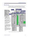
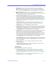
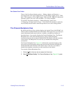
The MultiSwitch 700 Device View
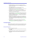
Port Status Color Codes
Three of the Port Status display options — Bridge, Admin, and Operator —
incorporate their own color coding schemes: for the Bridge option, green = FWD,
blue = DIS, magenta = LIS or LRN, orange = BLK, and red = BRK; for Admin and
Operator, green = ON, red = OFF, and blue = N/A (not available).
For all other Port Status selections — Bridge Mapping, Load, Errors,
I/F Mapping, I/F Speed, and I/F Type — color codes will continue to reflect the
most recently selected mode which incorporates its own color coding scheme.
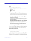
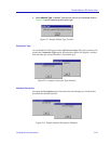
The Chassis Backplane View
By default, the Device View window displays the Logical View of the DLM6C-AA
Chassis and an installed MultiSwitch 700 module. The Logical View provides port
status information and access to device-, module-, and port-level menus, as
described above. You can also display the Chassis Backplane View. The Chassis
Backplane View of the hub indicates the five point-to-point backplane
connections between the monitored MultiSwitch 700 module and other modules
in the chassis. The Backplane View also lets you disable those backplane
connections.
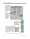
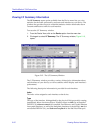
The Chassis Backplane View, Figure 2-5, indicates the operational status of the
five point-to-point backplane connections between the monitored MultiSwitch
700 module and other modules in the chassis slots. It also lets you enable or
disable the backplane connections to other modules in the chassis.
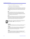
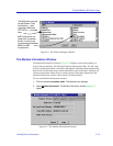
To access the Chassis Backplane View:
1. Click on V
iew in the menu bar to access the View menu.
2. Select B
ackPlane Config. The Chassis Backplane View, Figure 2-5, opens.