


Viewing Device Information 2-17
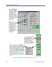
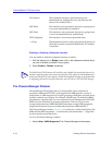
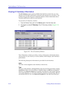
The MultiSwitch 700 Device View
The backplane connections are indexed 1–5, where 1 indicates the connection to
first slot in the chassis and 5 indicates the connection to the last slot.
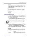
Backplane View Bridge Display Form
When the Backplane View display form is in the default Bridge mode, each
connection is represented by a color-coded text field as follows:
FWD (Green) The interface is on-line and ready to forward packets
across the MultiSwitch 700 from one module to another.
DIS (Blue) Bridging at the interface has been disabled by
management; no traffic can be received or forwarded on
this interface, including configuration information for
the bridged topology.
LIS (Magenta) The interface is not adding information to the filtering
database. It is monitoring Bridge Protocol Data Unit
(BPDU) traffic while preparing to move to the
forwarding state.
LRN (Magenta) The Forwarding database is being created, or the
Spanning Tree Algorithm is being executed because of a
network topology change. The interface is monitoring
network traffic, and learning network addresses.
BLK (Orange) The interface is on-line, but filtering traffic from going
across the MultiSwitch 700 from one module to another.
Bridge topology information will be forwarded by the
interface.
BRK (Red) The interface has malfunctioned.
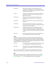
Backplane View Interface Display Form
When the Backplane View is in Interface mode, each connection is represented by
a color-coded text field that indicates a combination of the interface’s
Administrative status, Operational status, and Link status.
The following status conditions are supported:
UNK (Gray) NetSight Element Manager cannot determine the
backplane interface’s Administrative, Operational, or
Link status.
ON (Green) The backplane interface is operational (up) and
administratively enabled. Link status is linked, or not
applicable to the interface.