


Installing Optional Network Expansion Modules
3-4 Installation
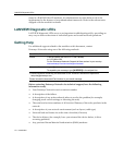
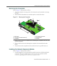
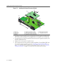
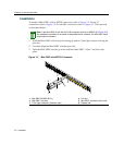
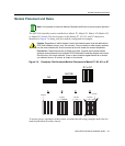
Figure 3-2 Installing the Network Expansion Module
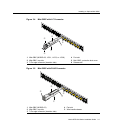
2. Usethetwosavedcoverplatescrewstofastenthenetworkexpansionmoduletothe
DFE‐Goldmodulefrontpanel.Donottightenthetwocoverplatescrewsatthistime.
3. Usethesavedscrewfromthe standofftofastenthenetworkexpansionmoduletothe
standoff. Tightenthescrew.
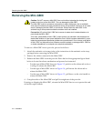
4. Tightenthetwo
front‐panelcoverplatescrews.
5. Thiscompletesthenetworkexpansionmoduleinstallation.ToinstallMini‐GBICsinto
thenetworkexpansionmodule,proceedto“InstallinganOptionalMini‐GBIC”on
page 3‐5fortheMini‐GBICinstallationinstructions.Otherwise,proceedto“Module
PlacementandRules”onpage 3‐9toinstallthe
DFEmoduleintothechassis.
1 Screw (1) 4 Optional expansion module 7 Main board connectors
2 Main bo\ard 5 DFE-Gold module
front panel 8 Coverplate screws (2)
3 Standoff 6 Expansion module connectors
COM
OFFLINE/
RESET
MGMT
CPU
1
2
3
GROUP
SELECT
1X
11X
13X
4
12X
14X
23X
24X
25X
26X
35X
36X
37X
38X
47X
48X
G
R
O
U
P
1
G
R
O
U
P
2
G
R
O
U
P
3
G
R
O
U
P
4
GROUP
1
2
3
4
5
6
7
8
9
10
11
12
4G4282-4 9
Gb ENET
DFE
Á
1
2
3
4
5
6
1
2
3
4
5
6
7G-6MGBIC-A
Ç
Ã
Ä
Å
Æ
À
Â