


Memory Locations and Replacement Procedures
Matrix DFE-Gold Series Installation Guide B-3
Memory Locations and Replacement Procedures
IntheeventthattheDualIn‐LineMemoryModule(DIMM)orDRAMSingleIn‐line
MemoryModule(SIMM)(FLASHmemory)needstobereplaced,thefollowingsections
describehowtoaccess,locateandreplacethesememorymodules.Ifyouhavequestions
concerningthereplacementofeithermemorymodule,referto
thesection,“Getting
Help,”onpage 1‐8fordetailsonhowtocontactEnterasys Networks.
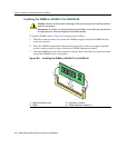
Location of DRAM SIMM and DIMM Memory Modules
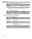
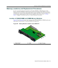
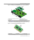
Figure B‐2andFigure B‐3showthelocationsoftheDRAMSIMMandDIMMontheeach
mainboardofthe4G4202‐72 andthe4G4282‐49,respectively.
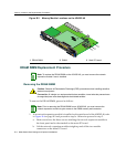
Figure B-2 Memory Module Locations on the 4G4202-72
1 DRAM SIMM
1
1. This is not considered a field replaceable unit on the 4G4202-72.
2 DIMM 3 Main PC board
À
Á
Â
COM
OFFLINE/
RESET
GROUP 3
GROUP 1
GROUP 2
CPU
MGMT
GROUP
1
2
3
GROUP
SELECT
1X
6X
7X
12X
13X
18X
19X
24X
4G4202-7 2
Gb ENET
À
Á
Â
COM
OFFLINE/
RESET
GROUP 3
GROUP 1
GROUP 2
CPU
MGMT
GROUP
1
2
3
GROUP
SELECT
1X
6X
7X
12X
13X
18X
19X
24X
4G4202-7 2
Gb ENET