


Setting the Mode Switches
B-2 Mode Switch Bank Settings and Optional Installations
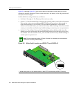
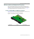
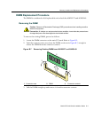
Figure B‐1throughFigure B‐3showthelocationofthemodeswi tchesand theswitch
settingsfornormaloperation.Theseswitchesaresetatthefactorytotheoffpositionand
rarelyneedtobechanged.
Switchdefinitionsandpositionsareasfollows:
•Switches1through6–ForEnterasys Networksuseonly.
•Switch7–ClearPersistentData.ChangingthepositionofthisswitchclearsPersistent
Dataonthenextpower‐upofthemodule.(PersistentDatareferstodatastoredin
non‐volativememory,orNVRAM.)Alluser‐enteredparameters,suchastheIP
addressandmodulenames,areresettothe
factorydefaultsettings.Oncethemodule
resets,youcan eitherusethefactorydefaultsettingsorreenteryourownparameters.
•Switch8–ClearAdminPassword.Changingthepositionofthisswitchclearsthe
adminpassword,andrestoresthefactorydefaultpasswordonthenextpower‐upof
themodule.Once
themoduleresets,youcaneitherusethefactorydefaultsettingsor
reenteryourownpassword.
Figure B-1 Mode Switch Location on 4G4202-72 and 4G4282-49
Note: Do not change the position of Switch 8 unless it is necessary to reset the admin
password to its factory default setting.
1 Mode switch pack is in the same location on both DFE-Gold modules (4G4202-72 shown)
12345678
ON
À
COM
OFFLINE/
RESET
GROUP 3
GROUP 1
GROUP 2
CPU
MGMT
GROUP
1
2
3
GROUP
SELECT
1X
6X
7X
12X
13X
18X
19X
24X
4G4282-4 9
Gb ENET