


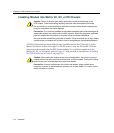

Installing the DFE Module into a Chassis
Matrix DFE-Gold Series Installation Guide 3-13
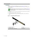
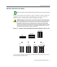
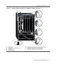
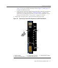
Figure 3-1 Installing Module into Matrix E7 or Matrix N7 Chassis (E7 shown)
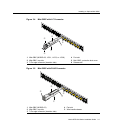
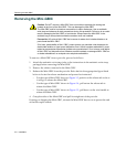
1 Card guides 5 Upper/lower locking tabs (in proper open position)
2 Slot number 1 (Left-most slot is 1.) 6 Upper/lower locking tab (in closed position)
3 Module card 7 Backplane connectors (power and FTM2)
4 Metal back panel
1
SERIES
E7
45
6
7
23
50/60Hz
LINE
100-125V~12A
200-240V~6A
50/60Hz
LINE
100-125V~12A
200-240V~6A
ACON
1
0
POWER FAN
PS1
50/60Hz
LINE
100-125V~12A
200-240V~6A
50/60Hz
LINE
100-125V~12A
200-240V~6A
ACON
1
0
POWER FAN
PS2
COM
OFFLINE/
RESET
MGMT CPU
1
2
3
GROUP
SELECT
1X
11X
13X
4
12X
14X
23X 24X
25X 26X
35X 36X
37X 38X
47X 48X
G
R
O
U
P
1
G
R
O
U
P
2
G
R
O
U
P
3
G
R
O
U
P
4
GROUP
1
2
3
4
5
6
7
8
9
10
11
12
4G4282-49
Gb ENET
Æ
Å
Å
Á
Ã
Â
À
Ä
Ä