


Memory Locations and Replacement Procedures
B-4 Mode Switch Bank Settings and Optional Installations
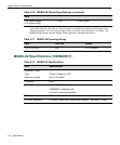
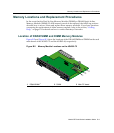
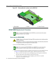
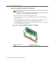
Figure B-3 Memory Module Locations on the 4G4282-49
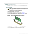
DRAM SIMM Replacement Procedure
Removing the DRAM SIMM
ToremovetheDRAMSIMM,proceedasfollows:
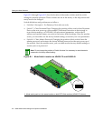
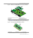
1. Ifannetworkexpansionmoduleisinstalledonthemainboardofthe4G4282‐49,refer
toFigure B‐4onpage B‐5and proceedtostep1a.Otherwiseproceedtostep2.
a. Removeandsavethethreescrewsattachingthenetworkexpansionmodule
to
thefrontpanelandtothestandoffonthemainPCboard.
b. Liftthenetworkexpansionmodulestraightupandoffthetwomodule
connectorsonthemainPCboard.
1 DRAM SIMM 2 DIMM 3 Main PC board
À
Á
Â
COM
OFFLINE/
RESET
MGMT
CPU
1
2
3
GROUP
SELECT
1X
11X
13X
4
12X
14X
23X
24X
25X
26X
35X
36X
37X
38X
47X
48X
G
R
O
U
P
1
G
R
O
U
P
2
G
R
O
U
P
3
G
R
O
U
P
4
GROUP
1
2
3
4
5
6
7
8
9
10
11
12
4G4282-4 9
Gb ENET
DFE
1
2
3
4
5
6
1
2
3
4
5
6
7G-6MGBIC-A
Note: To replace the DRAM SIMM on the 4G4282-49, you must remove the network
expansion module if one is installed.
Caution: Observe all Electrostatic Discharge (ESD) precautions when handling sensitive
electronic equipment.
Precaución: Al trabajar con equipos electrónicos sensibles, tome todas las precauciones
de seguridad para evitar descargas de electricidad estática.
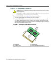
Note: Prior to removing the DRAM SIMM from a 4G4282-49, you must remove the
network expansion module to gain access to the DIMM memory and connector.