


Memory Locations and Replacement Procedures
Matrix DFE-Gold Series Installation Guide B-5
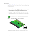
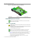
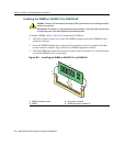
Figure B-4 NEM Removal and DRAM SIMM Connector Location on 4G4282-49
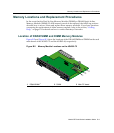
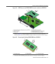
2. RefertoFigure B‐5.PushtheconnectorarmsawayfromtheDRAMSIMMand
simultaneouslylifttheDRAMSIMMenoughtoreleaseitfromtheconnectorfingers.
Figure B-5 Removing the Existing DRAM SIMM from 4G4282-49
3. RotatetheDRAMSIMMupward,thenremoveitfromtheconnectorfingers.
1 Network Expansion Module (not on all DFEs) 4 DFE module front panel
2 Main PC board 5 Module connectors on main board
3 Screws (3) 6 DRAM SIMM memory module
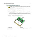
1 Connector arms 2 DRAM SIMM 3 Connector fingers
COM
OFFLINE/
RESET
MGMT
CPU
1
2
3
GROUP
SELECT
1X
11X
13X
4
12X
14X
23X
24X
25X
26X
35X
36X
37X
38X
47X
48X
G
R
O
U
P
1
G
R
O
U
P
2
G
R
O
U
P
3
G
R
O
U
P
4
GROUP
1
2
3
4
5
6
7
8
9
10
11
12
4G4282-4 9
Gb ENET
DFE
Â
1
2
3
4
5
6
1
2
3
4
5
6
7G-6MGBIC-A
À
Ã
Â
Á
Ä
Å
À
À
Á
Â