


1-5
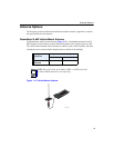
Determining the Antenna Locations
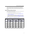
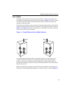
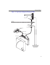
Line of Sight
The shape of the radio beam, defined as the Fresnel Zone, is widest in the middle. The
Fresnel Zone is shown as the gray area between the antennas in Figure 1-1. The exact shape
and width of the Fresnel Zone is determined by the distance between the antenna and
frequency of the radio signal.
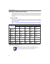
The radius of the radio beam, shown as the lower half of the Fresnel Zone, is the distance
from the center of the beam outward in any direction. The length of the radius is shown in
Table 1-1 and Table 1-2 as the line of sight clearance. The length of the radius is not based
on the data rate and the type of antenna.
Figure 1-1: Fresnel Zone and Line of Sight Clearance
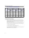
If a significant part of the Fresnel Zone is obstructed, a portion of radio energy is lost,
resulting in reduced performance. For optimal performance, ensure that the antenna
products you choose, in combination with the height of the antenna installation above
ground, provide sufficient clearance to allow your antenna installation to cover the distance
between the two sites.
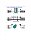
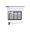
Obstacles within the line of sight can significantly reduce the distance and performance.
Obstructions include neighboring buildings, trees, and power lines as shown in Figure 1-2.