


Installation Overview
3-2
Installation Overview
The installation process is summarized in the following steps. The following sections in this
chapter provide additional details.
1. Make sure the APs are mounted and configured as specified in Chapter 2.
2. Check the cable connectors to verify that they are the correct polarity for your
installation.
3. Plan and implement a grounding system that meets local electrical codes and safety
standards.
4. Install the RoamAbout Lightning Protector.
5. Provide and install an antenna support structure as necessary. Make sure that the
support structure is connected to the grounding system.
6. Connect the exposed metal connectors of the low-loss antenna cable to the grounding
system.
7. Mount the antenna to the support structure.
8. Connect the antenna cables.
9. Route and connect the low-loss antenna cable to the RoamAbout Lightning Protector
that has been installed indoors.
10. Connect the cable assembly from the RoamAbout PC Card in the AP to the Lightning
Protector.
11. Run the AP Manager Link Test program to aim the antenna and verify optimal
placement.
12. After verifying that the communications link is fully operational, secure all cables and
use weatherproofing tape to seal all outdoor connectors.
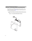
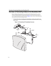
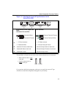
Verify Component Connector Polarity
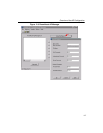
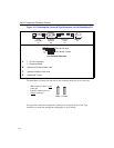
Before you start the antenna installation, refer to Figure 3-1 (Access Point 2000) and
Figure 3-2 (RoamAbout R2) to verify that the polarity of each connector is correct for your
installation. The components supplied with your outdoor antenna kit are configured with
either Standard-N connectors or Reverse Polarity-N connectors, subject to the country
where the kit was purchased.