


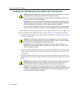
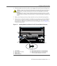
DFE Module Placement and Installation Rules
3-4 Installation
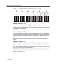
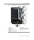
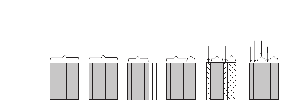
Figure 3-1 Examples, Module Placement in Matrix E7 Chassis
Example 1 (Figure 3-1, A)
ShowsthechassisfullypopulatedwithDFE modules(7xxxxx).Thesemodules
communicatewitheachotherviatheFTM2chassisbackplaneandactasasingle
switchingentitywithoneIPaddress.TheDFE modulesareconfiguredusingaCommand
LineInterfacesetofcommands.
Rule:DFE modulescanbeinstalledinanyavailablechassis
slotintheMatrixE7chassis.
Example 2 (Figure 3-1, B)
Showsthechassisfullypopulatedwiththirdgenerationmodules(6x3xx).Thesemodules
canalsobeinstalledinanyavailablechassisslotintheMatrixE7chassis,butoperateas
individualmoduleswithseparateIPaddresses.EachmoduleisconfiguredusingLocal
Management.
Rule:The6x3xxmodulescanbeinstalledinany
availablechassisslotintheMatrixE7
chassis.
Example 3 (Figure 3-1, C)
Showschassisslots1through5populatedwithfirstandsecondgenerationmodules
(6x1xxand6x2xx).Ifa6x1xxor6x2xxseriesmoduleisinstalledinslot6or7,itwill
operateinstandalonemode(nobackplaneconnectivity).Likethe6x3xxmodules,the
6x1xxand6x2xxmodulesoperateasindividual
moduleswithseparateIPaddresses,and
eachoneisconfiguredusingLocalManagement.
Rule:The6x1xxand6x2xxmodulescancommunicatewitheachotherwhentheyare
installedinchassisslots1through5intheMatrixE7chassis.Ifinstalledinslot6or7,they
operateinstandalonemode.
7XXXXX7H43X-XX
6X3XX
6X3XX
6X2XX
6X1XX
1 2 3 4 5 6 7
6X1XX
6X2XX
+
6X3XX
6X3XX
1 2 3 4 5 6 7
6X1XX
6X2XX
1 2 3 4 5 6 7
6X3XX
1 2 3 4 5 6 7
7XXXXX
1 2 3 4 5 6 7 1 2 3 4 5 6 7
6X3XX
6X3XX
6X2XX
7XXXXX
6X1XX
A EDCB
F