


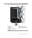
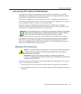

Preparing to Install into a Chassis
3-8 Installation
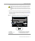
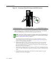
3. Alignthemodulecardbetweentheupperandlowercardguidesofthedesiredslot
andslideitintothechassis,takingcarethatthemoduleslidesinstraight.SeeCaution
below.
4. Slidethemoduleintotheslotuntilyoucanengagethetopandbottomlockinglevers.
5. RefertotheCaution
above,thenrotatethetwoleversintotheclosedposition.
6. Ifthechassisinwhichthemoduleisinstalledwaspowereddownfortheinstallation,
turnthepowersupplieson.ChecktoseethatthemoduleCPULEDsettlesatsolid
greenafterafewminutes.IftheLEDdoesnot
turnsolidgreen,refertoChapter 4for
troubleshootingdetails.
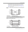
Caution: Due to the amount of force needed to properly seat the module connectors into
the backplane connectors, it is best to apply force to the end of the levers to insert (or
eject) the module. Otherwise, damage could result to the module and chassis.
Precaución: Para colocar los conectores del módulo en los conectores del panel
posterior correctamente es necesario hacer bastante fuerza, por ello, para insertar o quitar
el módulo, se recomienda concentrar la fuerza en el extremo de las palancas. Si no lo
hace, podría dañar el módulo y el chasis.
Caution: In step 5, do not force the locking levers to the point that they touch the face of
the front panel. Forcing the locking levers to this point could damage the module and
chassis.
Precaución: En el paso 5, tenga cuidado de no llevar las palancas de cierre a un punto
en donde estén en contacto con el panel frontal. Si lo hace, podría dañar el módulo y/o el
chasis.