


Connecting to the Network
DFE-Platinum Series Hardware Installation Guide 3-15
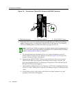
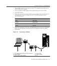
e. VerifythattheRJ45connectorsonthetwistedpairsegmenthavetheproper
pinoutsandcheckthecableforcontinuity.Typically ,acrossovercableisused
betweenhubdevices.Astraight‐throughcableisusedtoconnectbetween
switchesorhubdevicesandanenduser(computer).RefertoFigure 3‐5
and
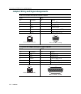
Figure 3‐6forfour‐wireRJ45connections.RefertoFigure 3‐7andFigure 3‐8 for
eight‐wireRJ45connections.
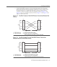
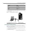
Figure 3-5 Four-Wire Crossover Cable RJ45 Pinouts, Connections Between Hub
Devices
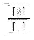
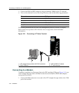
Figure 3-6 Four-Wire Straight-Through Cable RJ45 Pinouts, Connections
Between Switches and End User Devices
1 RJ45 device port 3 RJ45-to-RJ45 crossover cable
2 Other device port 4 RX+/RX- and TX+/TX- connections.
These connections must share a common color pair.
1 RJ45 device port 3 RJ45-to-RJ45 straight-through cable
2 Other device port 4 RX+/RX- and TX+/TX- connections.
These connections must share a common color pair.
TX+
TX
RX+
RX 2
1
3
6
TX+
TX
2
1
3
6
RX+
RX
ÀÁ
Â
Ã
TX+
TX
RX+
RX 2
1
3
6
TX+
TX
2
1
3
6
RX+
RX
ÀÁ
Â
Ã