


Graphics
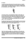
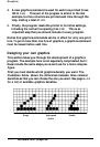
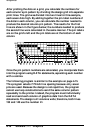
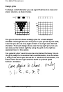
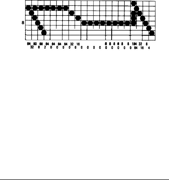
After plotting the dots on a grid, you calculate the numbers for
each column’s pin pattern by dividing the design grid into separate
print lines. The grid was divided into two lines for this example,
each seven dots high. By adding together the pin label numbers of
the dots in each column, you can calculate the number needed to
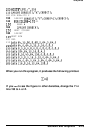
produce the desired column pin pattern. The results for the first
line are shown in the figure below; the numbers needed to produce
the second line were calculated in the same manner. The pin labels
are on the grid’s left and the pin totals are at the bottom of each
column.
128
64
32
16
8
4
2
1
t
I
f3
I
I
I
f
I
I /
I I
I
046088646464e422l6
88
8
8
8
(I
88184328
2
3282000000000000008)184
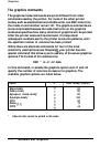
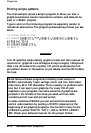
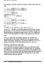
Once the pin pattern numbers are calculated, you incorporate them
into the program using DATA statements, separating each number
with a comma.
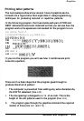
The following program is similar to the example on page 4-15.
This program selects 7/72inch line spacing because only seven
pins are used. Because the design is not repetitive, the program
cannot use loop constructions to send the same column pattern
repeatedly to the printer. Instead, the program must individually
read and send each column of graphics data from the DATA
statements. The design is 41 columns wide; therefore, both lines
130 and 140 use the number 41.
4-18
Software
and
Graphics