Configuring the Host Computer for RS-232 Serial Interface
RS-232 Cabling
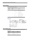
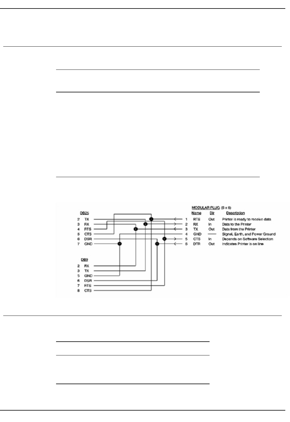
RS-232 cable pinouts are shown in the table below. For details on RS-232 signal names,
consult the RS-232 Standard documentation.
Origination
(Mod. 8 x 8)
Termination
(DB9S)
Name Dir Description
1 8 RTS Out Printer is ready to receive data
2 3 RX In Data to the printer
3 2 TX Out Data from the printer
4 5 GND -- Signal, earth, and power ground
5 7 CTS In Depends on software selection
6 6 DTR Out Indicate printer is online
Modular Plug
RS-232 Signal Levels
The serial interface uses standard RS-232 signal levels as shown in the table below:
Signal Level Input Output
MARK (1) -27 V to -5 V -5 V
SPACE (0) +5 V to +27 V +12 V
RS-232 signal levels.
4


