


Krautkramer USN 52R/USN 52L Issue 05, 02/00 5-19
– Increase ZERO until the correct sound path value for
the echo is displayed.
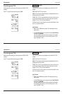
Example:
– Carry out calibration on a 25 mm thick test piece for
a calibration range of 100 mm.
– Set RANGE to 100 mm
– Set ZERO to 0.000 s
– If possible, when in MTL VEL, set an approximate
value for the sound velocity
– Set MEASURE to MULTECHO
– Adjust the gates so that the first echo is evaluated in
Gate a and the second in Gate b.
Attention: Be careful of node errors when setting the
threshold!
– Adjust the sound velocity MTL VEL until the
displayed reading (sound path between the two
backwall echoes) corresponds to the actual
thickness of the test object. If necessary, you have
to readjust the gate parameters.
– Set MEASURE to 0 TO 1st
– Increase ZERO until the correct sound path for the
echo in the gate is displayed.
Straight-beam probe with delay
Calibration with straight-beam probes, which have a
greater delay path, mainly corresponds to the above
calibration for straight-beam probes which only have the
protection layer as a delay path.
Unlike the above procedure, you have to start by mak-
ing the following adjustments:
– Set DELAY and ZERO to 0
– Preadjust ZERO so that the first interface echo is at
the zero point of the scale.
– Adjust RANGE so that, with a known sound
velocity, the first interface echo and at least the first
backwall echo appear, and, with an unknown sound
velocity, at least two backwall echoes appear before
the second interface echo.
– From this point, proceed the same as for both
previous cases.
USN 52R/USN 52L calibration Operation
Krautkramer USN 52R/USN 52L Issue 05, 02/00 5-19
– Increase ZERO until the correct sound path value for
the echo is displayed.
Example:
– Carry out calibration on a 25 mm thick test piece for
a calibration range of 100 mm.
– Set RANGE to 100 mm
– Set ZERO to 0.000 s
– If possible, when in MTL VEL, set an approximate
value for the sound velocity
– Set MEASURE to MULTECHO
– Adjust the gates so that the first echo is evaluated in
Gate a and the second in Gate b.
Attention: Be careful of node errors when setting the
threshold!
– Adjust the sound velocity MTL VEL until the
displayed reading (sound path between the two
backwall echoes) corresponds to the actual
thickness of the test object. If necessary, you have
to readjust the gate parameters.
– Set MEASURE to 0 TO 1st
– Increase ZERO until the correct sound path for the
echo in the gate is displayed.
Straight-beam probe with delay
Calibration with straight-beam probes, which have a
greater delay path, mainly corresponds to the above
calibration for straight-beam probes which only have the
protection layer as a delay path.
Unlike the above procedure, you have to start by mak-
ing the following adjustments:
– Set DELAY and ZERO to 0
– Preadjust ZERO so that the first interface echo is at
the zero point of the scale.
– Adjust RANGE so that, with a known sound
velocity, the first interface echo and at least the first
backwall echo appear, and, with an unknown sound
velocity, at least two backwall echoes appear before
the second interface echo.
– From this point, proceed the same as for both
previous cases.
USN 52R/USN 52L calibration Operation