


5-20 Issue 05, 02/00 Krautkramer USN 52R/USN 52L
Calibration with angle-beam probes
Known sound velocity
In this case, it is sufficient when there is an echo from
a known reflector with a known distance, e.g. the arc of
the calibration block V1, V2.
– Enter known sound velocity MTL VEL
– Set Gate a to the first echo
– Set ZERO so that the correct value is displayed in
the measurement line “S=...”.
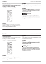
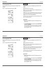
Example:
Calibration of the 100 mm range for steel (trans) using
calibration block V2
– Enter sound velocity MTL VEL (3255 m/s)
– Set RANGE to 100 mm.
– Set DELAY and ZERO to 0.
– Couple the probe and peak the first echo from the
25 mm radius of V2.
– Set Gate a to the first arc echo.
– Adjust ZERO so that “S=25" is displayed in the
measurement line.
The display range is now calibrated. For the measure-
ment you can now enter the values for ANGLE, X-
VALUE and THICKNESS.
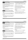
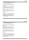
Unknown sound velocity
In this case you will require a calibration block made of
the test material. A semicylinder is suitable for this
purpose.
Couple the probe to the plane of section of the
semicylinder with the radius R, and peak the first echo
from the semicircle. An echo sequence occurs with the
sound paths R, 3R, 5R, etc.
You apply these echoes for calibration the same as the
backwall echoes described above which come from a
plane-parallel calibration piece with vertical beaming.
Operation USN 52R/USN 52L calibration
5-20 Issue 05, 02/00 Krautkramer USN 52R/USN 52L
Calibration with angle-beam probes
Known sound velocity
In this case, it is sufficient when there is an echo from
a known reflector with a known distance, e.g. the arc of
the calibration block V1, V2.
– Enter known sound velocity MTL VEL
– Set Gate a to the first echo
– Set ZERO so that the correct value is displayed in
the measurement line “S=...”.
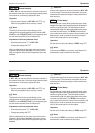
Example:
Calibration of the 100 mm range for steel (trans) using
calibration block V2
– Enter sound velocity MTL VEL (3255 m/s)
– Set RANGE to 100 mm.
– Set DELAY and ZERO to 0.
– Couple the probe and peak the first echo from the
25 mm radius of V2.
– Set Gate a to the first arc echo.
– Adjust ZERO so that “S=25" is displayed in the
measurement line.
The display range is now calibrated. For the measure-
ment you can now enter the values for ANGLE, X-
VALUE and THICKNESS.
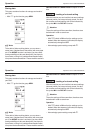
Unknown sound velocity
In this case you will require a calibration block made of
the test material. A semicylinder is suitable for this
purpose.
Couple the probe to the plane of section of the
semicylinder with the radius R, and peak the first echo
from the semicircle. An echo sequence occurs with the
sound paths R, 3R, 5R, etc.
You apply these echoes for calibration the same as the
backwall echoes described above which come from a
plane-parallel calibration piece with vertical beaming.
Operation USN 52R/USN 52L calibration