


2-2 Px Series Application Switch Installation and Configuration Guide
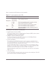
Table 2-1 describes the LED behavior on the SummitPx1.
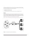
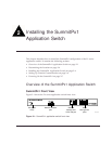
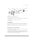
The front panel of the SummitPx1 has four ports:
• Gigabit Interface Connector (GBIC)
The Network Interface port is a Gigabit Interface Connector (GBIC) used to connect
the application switch to your local network.
• 100BASE-Tx Ethernet Management (RJ-45)
The Ethernet Management port (RJ-45 connector) is a 10/100 Mbps Ethernet
connection used for out-of-band management.
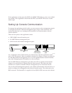
• Console (serial RJ-45)
The console port (serial RJ-45 connector) is used to connect a terminal for local
out-of-band management. The console operates at 9600 baud, 8 data bits, no parity,
one stop bit (8-N-1) with no hardware flow control.
Use the included DB-9 adapter to connect the console to a PC serial port, using a
straight (1-8, 1-8) cable, such as a standard category 3 or category 5 Ethernet cable.
The pinouts for the DB-9 adapter are shown in Table 2-2 on page 2-3.
If you are wiring the console port to a console server, you must use a null modem
cable (1-8, 8-1).
• AUX (serial RJ-45)
The AUX port (RJ-45 connector) has the same pin-outs as the console port. The AUX
port is used for remote out-of-band management.
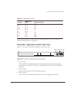
Table 2-1: Px series application switch LEDs
LED Color Indicates
Link Green
Yellow flashing
The 1000Base-T link is operational.
There is activity on this link.
Management Green flashing
■ Slow
■ Fast
Red
The Px series application switch is operating normally.
Power On Self Test (POST) in progress.
The Px series application switch has failed its POST.
Power Green
Red
The Px series application switch is powered up.
The Px series application switch is indicating a power or
temperature problem.