


30 XTP CrossPoint 1600 and 3200 • Remote Control 31XTP CrossPoint 1600 and 3200 • Remote Control
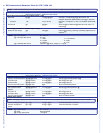
Command SIS Command
(Host to Unit)
Response
(Unit to Host)
Additional Description
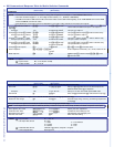
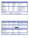
Audio output volume
Set the volume to a specic value
X@
*
X1%
V Out
X@
•Vol
X1%]
Example:
1*50v
Out01•Vol50
]
Set output 1 volume to 79%.
Increment volume
X@
+V Out
X@
•Vol
X1%]
Increase volume by 1 step.
Example:
1+V
Out01•Vol51
]
Decrement volume
X@
–V Out
X@
•Vol
X1%]
Decrease volume by 1 step.
Read output volume
X@
V
X1%]
Audio mutes
Audio mute, HDMI
X@
*1Z Amt
X@
*1
]
Mute output
X@
HDMI (embedded digital audio off).
Audio mute, analog
X@
*2Z Amt
X@
*2
]
Mute output
X@
analog (analog audio off).
Audio mute, both
X@
*3Z Amt
X@
*3
]
Mute all output
X@
audio (HDMI and analog audio off).
Audio unmute
X@
*0Z Amt
X@
*0
]
Unmute output
X@
(HDMI and analog audio on).
Read audio mute
X@
Z
X1)]
1 = mute on, 0 = mute off.
Global audio mute, HDMI
1*Z
Amt1
]
Mute all embedded digital audio outputs.
Global audio mute, analog
2*Z
Amt2
]
Mute all analog audio outputs.
Global audio mute, both
3*Z
Amt3
]
Mute all embedded digital and analog audio outputs.
Global audio unmute
0*Z
Amt0
]
Unmute all audio outputs.
NOTE: • = Space
X@
= Output number 01 – 16 or 32
X1)
= Mute 0 = off (unmuted) 2 = analog on (analog muted)
1 = HDMI on (HDMI muted) 3 = HDMI and analog on (both muted)
X1%
= Volume adjustment range 0 – 64 (1 dB/step except for 0-to-1, which is 22 dB) (default = 64 [0 dB])
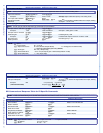
Command SIS Command
(Host to Unit)
Response
(Unit to Host)
Additional Description
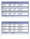
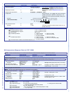
View video and audio mutes
View output mutes
E
VM
}
X1^
1
X1^
2
...
X1^
n
]
Each
X1^
response is the mute status of an output, starting
from output 1. n = either 16 or 32.
Example :
(XTP CrossPoint 3200)
E
VM
}
Audio is muted on outputs 2 and 3, video on output 5,
and video and audio on output 26. All other outputs are
unmuted.
Mut02201000000000000000000002000000
]
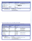
List Digital Sync Validation Processing (DSVP)
List sync of all inputs
0LS
X1&
1
X1&
2
X1&
3
...
X1&
n
]
16 or 32 (
n
)
X1&
s; each is the signal status of an input,
starting from input 1.
Example
(XTP CrossPoint 3200):
0LS
Input:
Response Status:
no input detected
input detected
1 2345
6
732
0 0 0 1 1 1 0 . . . 0
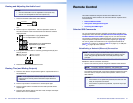
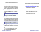
Lock (Executive) modes
NOTE: See Setting the front panel locks (executive modes) on page 18 for more information on the Lock modes.
Lock all front panel functions
1X
Exe1
]
Enable Lock mode 1.
Lock advanced front panel
functions
2X
Exe2
]
Enable Lock mode 2.
Unlock all front panel functions
0X
Exe0
]
Enable Lock mode 0.
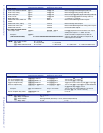
View lock status
X
X1*]
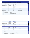
NOTE:
X1^
= Video and audio mute status 0 = no mutes 2 = audio mute
1 = video mute 3 = video and audio mute
X1&
= Signal detection status 0 = no input connected 1 = input connected
X1*
= Lock mode 0 = lock mode 0 (unlocked) 1 = lock mode 1 2 = lock mode 2